
Distributed direct-current micro-grid energy control method

A technology of DC microgrid and energy control, which is applied in parallel operation of DC power supplies, DC network circuit devices, collectors, etc., can solve the problems of energy supply, large error, and no energy control management, etc., to maintain stability and improve Accuracy, the effect of ensuring healthy operation

Inactive Publication Date: 2017-05-31
SOUTHWEST JIAOTONG UNIV
View PDF2 Cites 21 Cited by
  • Summary
  • Abstract
  • Description
  • Claims
  • Application Information

AI Technical Summary

Problems solved by technology

In the photovoltaic cell control unit, the maximum power output cannot be achieved, so that the utilization rate of renewable energy is low, and the photovoltaic cell cannot always provide energy for the system at the maximum power, resulting in waste of energy; The droop and anti-droop control method, the droop coefficient is determined by a simple linear relationship, resulting in a large error in the judgment of the energy balance of the system, and cannot accurately provide or absorb energy to the system, resulting in energy imbalance and system stability. Poor; in the current technology, fuel cells are rarely used as system backup power to provide energy for the system when the energy of the system is out of balance, so that once the photovoltaic cells and storage batteries provide insufficient energy for the system, the system will be paralyzed at a faster speed, and At present, some systems that use fuel cells are also very inefficient in the use of fuel cells, without reasonable energy control and management, resulting in waste of energy

Method used


Image

  • Distributed direct-current micro-grid energy control method
  • Distributed direct-current micro-grid energy control method
  • Distributed direct-current micro-grid energy control method

Examples


Embodiment Construction

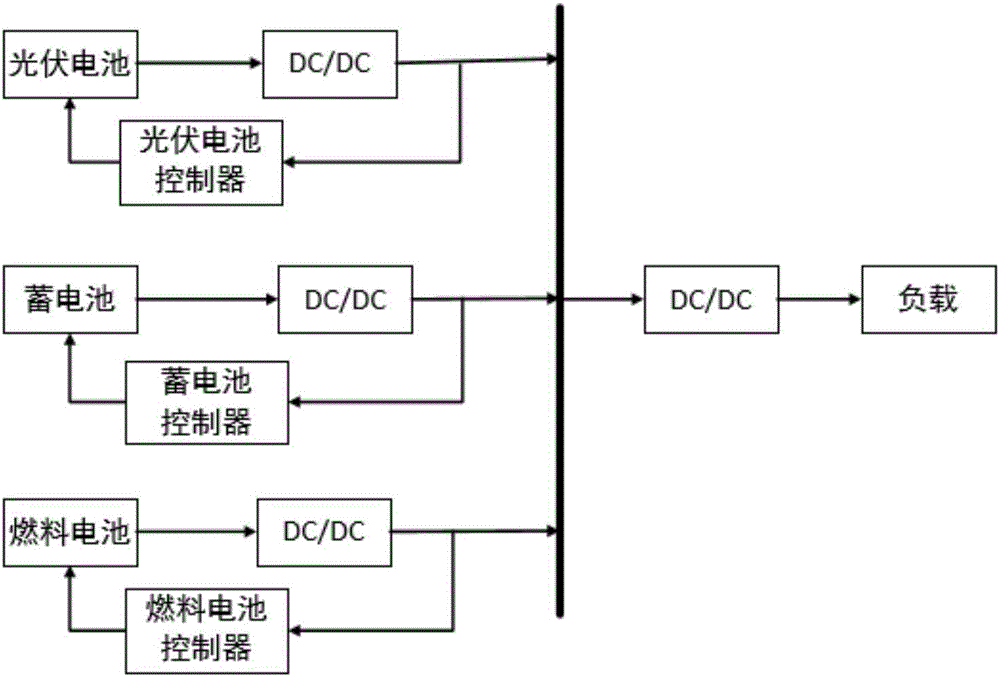
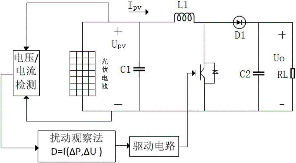
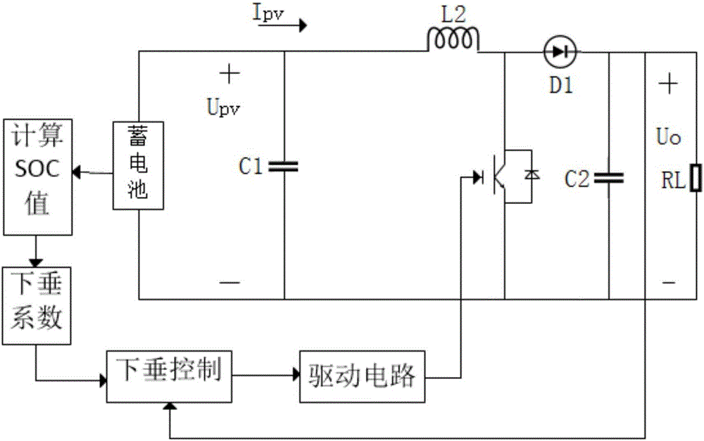
[0031] The present invention will be described in further detail below in conjunction with the accompanying drawings. In this embodiment, the photovoltaic cell disturbance tracking maximum power strategy is used to control the maximum power output of renewable energy; the battery self-adaptive adjustment droop coefficient control strategy is used to maintain the energy balance when the renewable energy power generation and load power fluctuate; the fuel cell optimal The economic operation strategy maintains the balance of the system to meet the energy demand of the load when the power generation is insufficient or the load is aggravated. Control the output power of the power supply side to realize the on-demand output of the load.

[0032]For the system, this embodiment adopts a distributed control topology, which can not only improve the stability of the system, but also communicate with the working states of other power sources at the same time. The system control block dia...


PUM


Abstract

The invention discloses a distributed direct-current micro-grid energy control method. The method combines a solar cell maximum power tracking strategy, uses disturbance tracing method to keep the solar cell transmitting in the maximum power all the time, and makes the best of energy produced by the solar cell to provide the energy for the system; Use the storage battery self-adapting droop coefficient control strategy. With the changing of the storage battery SOC, self-adapt the droop coefficient to enhance the accuracy of the storage battery controlling the system energy, and improve the stability of the system; Use fuel cell economic operation strategy to keep the fuel cell working in the stable stage of the ohms voltage, namely the economic running belt, and provide energy for the system when the solar cell and the storage battery cannot provide adequate energy for the system, and maintain the stability of the system.

Description

technical field [0001] The invention relates to the technical field of DC microgrid control, in particular to a distributed DC microgrid energy control method. Background technique [0002] At present, the known DC microgrid is connected to the DC bus by distributed power sources, energy storage devices, loads, etc., and the DC network is connected to the external AC grid through the power electronic inverter device. The AC and DC loads of the voltage level provide electric energy, and the fluctuation of the distributed power supply and the load can be adjusted by the energy storage device on the DC side. There are various types of power generation sources for DC microgrids, common ones are photovoltaic systems, fuel cells, etc. Among them, the fuel cell power generation utilization rate is relatively high, the pollution is small, the raw material is abundant, and it can be arranged in any position according to the needs, so the application range of the fuel cell in the DC ...

Claims


Application Information

Patent Timeline
Patent Type & Authority Applications(China)
IPC IPC(8): H02J1/10H02J7/35
CPCH02J1/10H02J7/35H02J2300/30Y02E10/56
Inventor 龚子元卢华歆余思儒向智莉周瑞兵梁星
Owner SOUTHWEST JIAOTONG UNIV
Learn More