
Delay Compensation Method for High Dynamic Motor Servo Control System

A servo control system and delay compensation technology, applied in the direction of motor generator control, control system, vector control system, etc., can solve the problems of feedback response curve amplitude attenuation and phase lag, etc., to improve dynamic performance, increase amplitude and frequency characteristics, and the effect of improving phase current accuracy

Active Publication Date: 2019-02-15
SHANGHAI AEROSPACE CONTROL TECH INST
View PDF3 Cites 0 Cited by
  • Summary
  • Abstract
  • Description
  • Claims
  • Application Information

AI Technical Summary

Problems solved by technology

In the actual application process, the electric steering gear requires the motor to meet the high-frequency dynamic response requirements between zero speed and the highest speed. It is difficult for the conventional control algorithm to make the motor meet both low-speed stable control and high-frequency dynamic response. Make some optimization adjustments to the control algorithm
[0003] The motor control system itself is an inertial delay system. With the increase of the frequency and amplitude of the control command, the amplitude of the feedback response curve will be greatly attenuated and the phase will lag significantly. The influence of the high-frequency dynamic response of the steering gear system, therefore, urgently needs to be improved

Method used


Image

  • Delay Compensation Method for High Dynamic Motor Servo Control System
  • Delay Compensation Method for High Dynamic Motor Servo Control System
  • Delay Compensation Method for High Dynamic Motor Servo Control System

Examples


Embodiment Construction

[0032] The present invention will be further elaborated below by describing a preferred specific embodiment in detail in conjunction with the accompanying drawings.

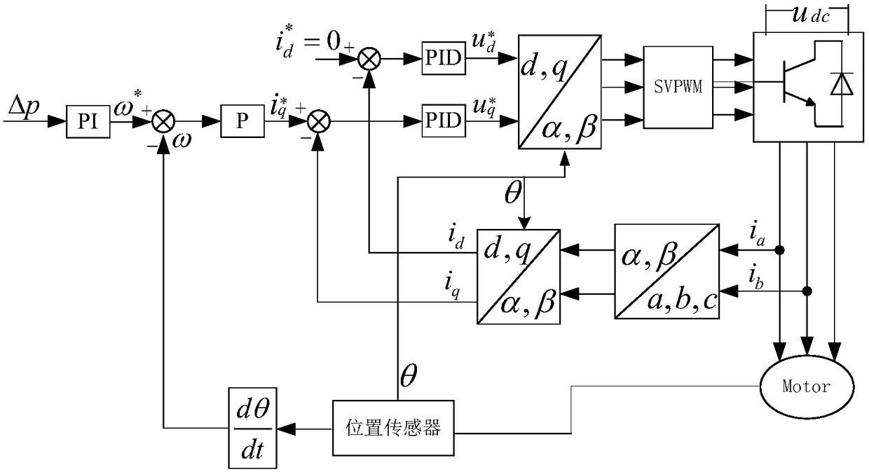
[0033] Such as figure 1 As shown, a delay compensation method for a high dynamic motor servo control system includes the following steps:

[0034] S1. Obtain the motion state information of the motor at the sampling moment of the current control cycle.

[0035] S2. Obtain the motion state information of the motor at the sampling time of the previous control cycle.

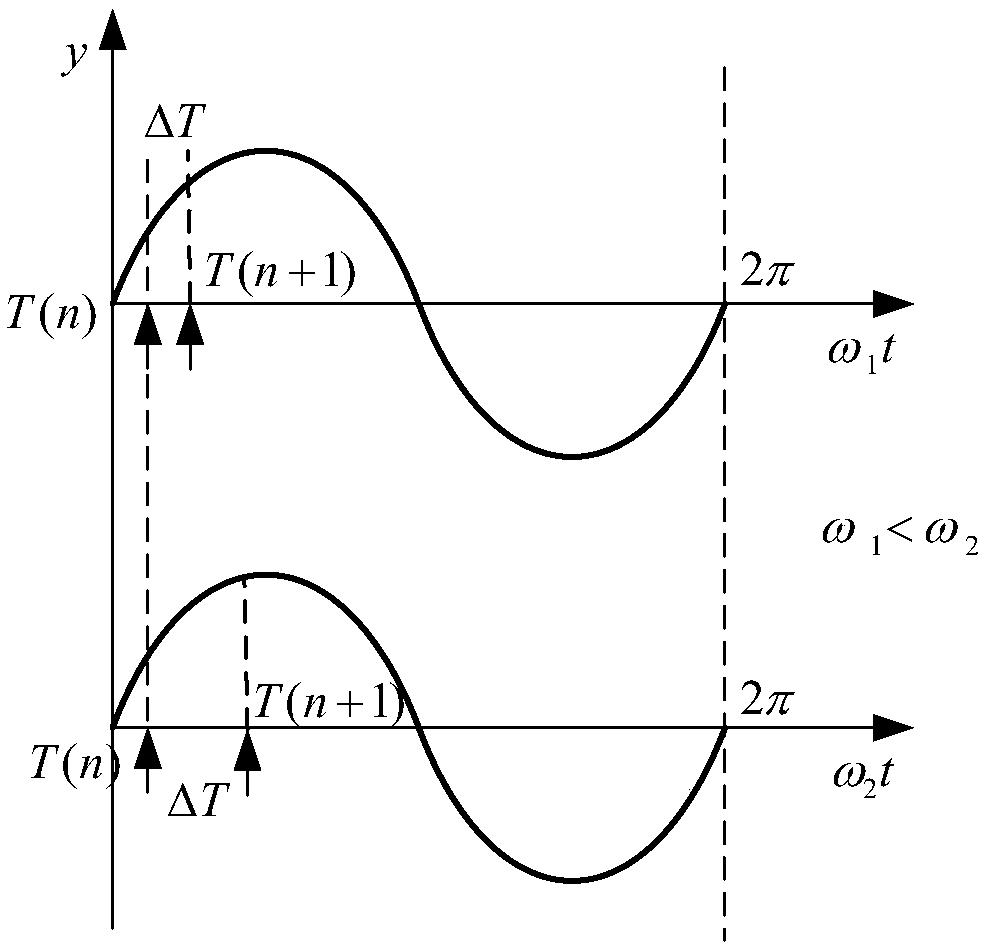
[0036] S3. Compensate the motor space control vector at the sampling time of the next control cycle according to the motor motion state information at the sampling time of the current control cycle and the motor motion state information at the sampling time of the previous control cycle to complete the delay of the high dynamic motor servo control system compensate.

[0037] Highly dynamic motor space vector control requires accurate phase current ...


PUM


Abstract

The invention discloses a time delay compensation method of a high-dynamic motor servo control system. The time delay compensation method comprises the following steps of obtaining motor motion state information at current control period sampling time; obtaining the motor motion state information at previous control period sampling time; and compensating a motor space control vector at the next control period sampling time according to the motor motion state information at the current control period sampling time and the motor motion state information at the previous control period sampling time and completing time delay compensation of the high-dynamic motor servo control system. The high-dynamic response performance of a motor is effectively improved and the efficiency of the motor is improved through reducing a data calculation error, caused by a program calculation time delay, of the motor control system; through the system employing three closed-loops of a position loop, a speed loop and a current loop, high-dynamic stable control of a motor steering gear system is achieved.

Description

technical field [0001] The invention relates to the technical field of motor control applied to an electric steering gear servo system, in particular to a delay compensation method for a high dynamic motor servo control system. Background technique [0002] With the development of motor control technology and power electronics technology, the motor used in the electric steering gear servo system gradually develops from DC motor to AC synchronous motor. The permanent magnet motor has the advantages of small size, high efficiency, and low loss, and is very suitable for the field of high-precision electric steering gear servo control. In the actual application process, the electric steering gear requires the motor to meet the high-frequency dynamic response requirements between zero speed and the highest speed. It is difficult for the conventional control algorithm to make the motor meet both low-speed stable control and high-frequency dynamic response. Make some optimization ...

Claims


Application Information

Patent Timeline
Patent Type & Authority Patents(China)
IPC IPC(8): H02P21/14
CPCH02P21/14
Inventor 张波汤伟张军苏伟杰
Owner SHANGHAI AEROSPACE CONTROL TECH INST
Learn More