Method for producing a brush-commutated direct-current motor

A technology of DC motor and pole teeth, applied in the field of brushed commutation DC motor, can solve the problem of asymmetric commutation current, and achieve the effect of reducing the structure space

Inactive Publication Date: 2017-05-31
布洛泽汽车部件制造沃尔兹堡有限公司
View PDF7 Cites 0 Cited by
  • Summary
  • Abstract
  • Description
  • Claims
  • Application Information

AI Technical Summary

Problems solved by technology

This causes an asymmetry in the commutation current

Method used


Image

  • Method for producing a brush-commutated direct-current motor
  • Method for producing a brush-commutated direct-current motor
  • Method for producing a brush-commutated direct-current motor

Examples


Embodiment Construction

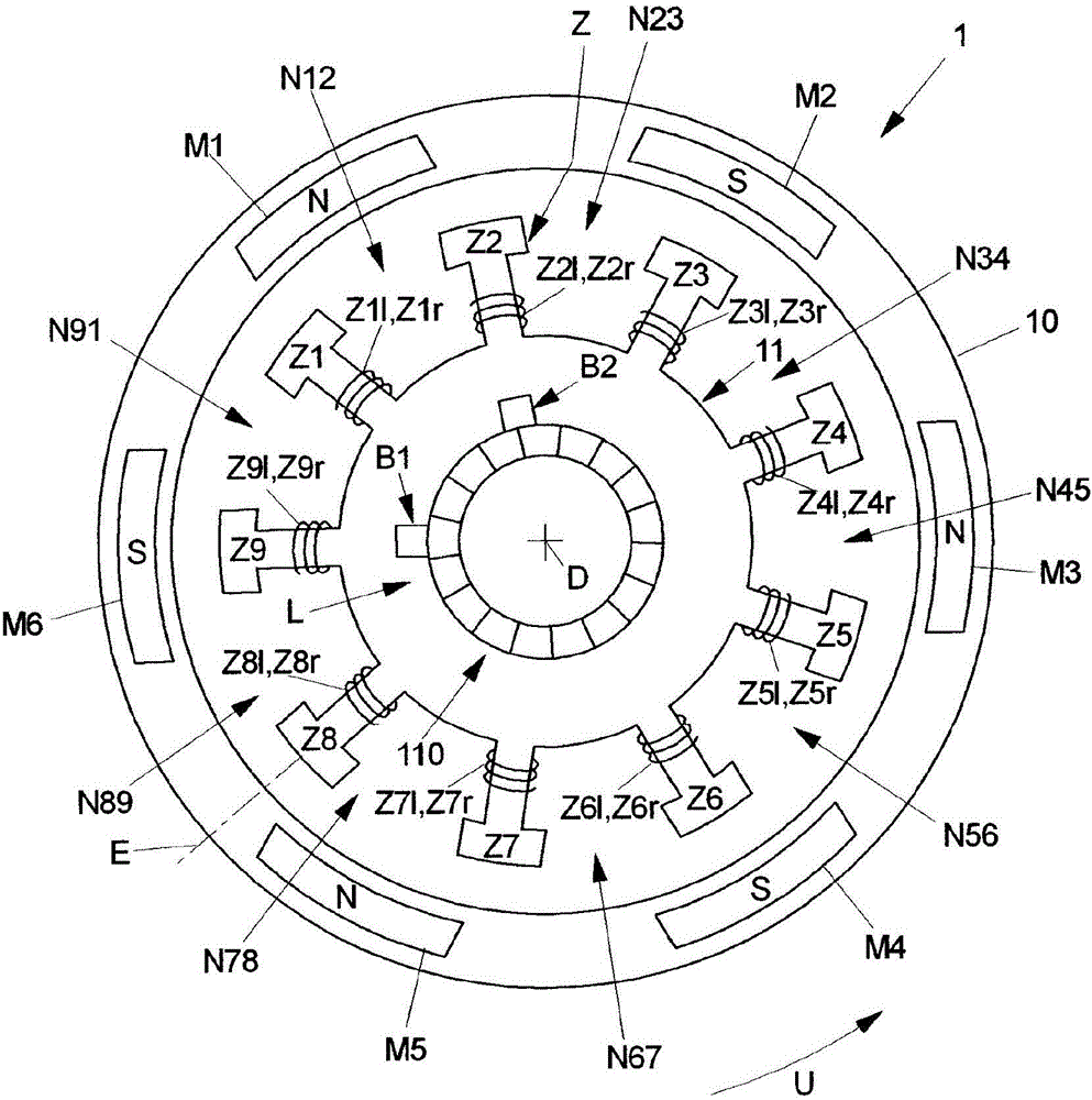
[0050] figure 1 A schematic illustration of a brush-commutated DC motor 1 with a stator 10 and a rotor 11 arranged on the stator 10 , rotatable about an axis of rotation D, is shown.

[0051] In a known manner, the stator 10 has a multiplicity of field poles M1 - M6 , which are formed by permanent magnets and arranged in the same manner on the stator 1 over a large area. Field poles M1 - M6 are directed towards rotor 11 by means of different, alternating poles N, S, so that in circumferential direction U south pole S always follows north pole S and vice versa.

[0052] In the exemplary embodiment shown, the stator 10 has exactly six field poles M1-M6.

[0053] The rotor 11 is arranged rotatably about the axis of rotation D on the stator 10 and, in the exemplary embodiment shown, has nine pole teeth Z1 - Z9 , which extend radially relative to the axis of rotation D along the direction of extension E, Pointing towards the stator 10 and separated from each other about the axis ...


PUM


Abstract

The invention relates to a brush-commutated direct-current motor comprising: a stator having a plurality of excitation poles; a rotor, which can be rotated about an axis of rotation in relation to the stator and which has a plurality of pole teeth, grooves arranged between the pole teeth, and coil windings arranged on the pole teeth; a commutator, which is arranged on the rotor; and a plurality of commutator bars, to which the coil windings are connected. In order to produce such a direct-current motor, the coil windings are arranged on the pole teeth in winding revolutions, in which a coil winding is wound on each pole tooth. According to the invention a first coil winding (Z1l-Z9l) wound around the pole tooth (Z1-Z9) in a first winding direction and a second coil winding (Z1r-Z9r) wound around the pole tooth (Z1-Z9) in a second winding direction opposite the first winding direction are arranged on each pole tooth (Z1-Z9), wherein in a first winding revolution the first coil windings (Z1l-Z9l) are wound on a first share of the pole teeth (Z1-Z9) and the second coil windings (Z1r-Z9r) are wound on a second share of the pole teeth (Z1-Z9) and in a second winding revolution the second coil windings (Z1r-Z9r) are wound on the first share of the pole teeth (Z1-Z9) and the first coil windings (Z1l-Z9l) are wound on the second share of the pole teeth (Z1-Z9). In this way, a method for producing a brush-commutated direct-current motor is provided which makes it possible to produce the direct-current motor in a simple manner in which the available packaging space is fully utilized.

Description

technical field [0001] The invention relates to a method for producing a brush-commutated DC motor according to the preamble of claim 1 and to a brush-commutated DC motor. Background technique [0002] A brush commutated DC motor includes a stator having a plurality of field poles and a rotor rotatable about an axis of rotation relative to the stator. The rotor has a plurality of pole teeth and slots arranged between the pole teeth which separate the pole teeth from one another in the circumferential direction around the axis of rotation. Coil windings are arranged on the pole teeth, which are energized during operation of the brush-commutated DC motor via a commutator arranged on the rotor and in this way are electrically driven in interaction with the field poles of the stator. The force of the motor acts on the rotor. The commutator comprises a plurality of laminations to which the coil windings of the rotor are connected via connecting arms. [0003] When producing a ...

Claims


Application Information

Patent Timeline
Patent Type & Authority Applications(China)
IPC IPC(8): H02K23/34H02K15/095
CPCH02K23/28H01R39/32H01R43/06H02K13/006H02K13/04H02K15/0056H02K15/095H02K23/30H02K23/34
Inventor 阿克拉姆·本埃拉尔沃尔特·罗德诺贝特·海姆约翰尼斯·巴托舍克
Owner 布洛泽汽车部件制造沃尔兹堡有限公司
Why Eureka
Try Eureka