Machining process for drip tray

A processing technology and technology of drip tray, applied in the field of processing technology of drip tray, can solve problems such as tearing of drip tray

Inactive Publication Date: 2017-06-06
ZHONGSHAN HENGRUN METAL PROD
View PDF6 Cites 0 Cited by
  • Summary
  • Abstract
  • Description
  • Claims
  • Application Information

AI Technical Summary

Problems solved by technology

[0004] At the same time, since the drip tray with a larger size may be torn when stamped, we also need to make corresponding improvements.

Method used


Image

  • Machining process for drip tray
  • Machining process for drip tray
  • Machining process for drip tray

Examples


Embodiment Construction

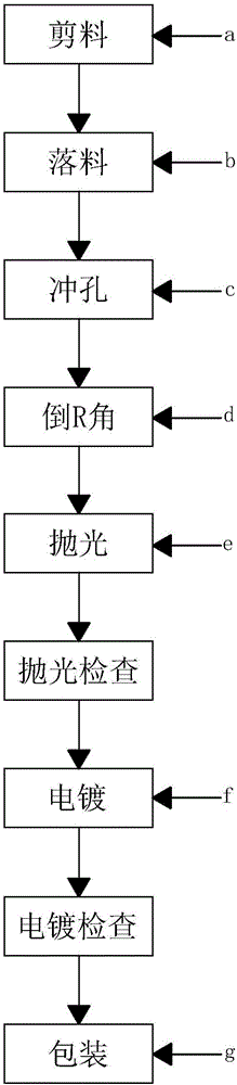
[0036] like figure 1 , figure 2 , Figure 6 , Figure 7 Shown, the processing technology of a kind of drip tray of the present invention comprises the following steps:

[0037] a, cutting material, cutting the sheet material into several strips 1;

[0038] In this embodiment, the alloy material of SUS201 is selected, the thickness of the material is T=2.7mm, and the size is 1220mm*2440mm. The manufacturer uses this material sheet to produce small and large drip trays with different specifications. When producing small drip trays, each The material sheet is cut into 22 strips 1 with a width of 106.7 mm, and each material sheet is cut into 11 strips 1 with a width of 219.34 mm when producing a large drip tray.

[0039] b. Blanking, fix the strip 1 in a on the working position of the hydraulic press, and stamp it into a drip tray of a preset shape;

[0040] like image 3 , Figure 8 As shown, in this embodiment, the strip material 1 with a width of 106.7 mm is stamped to ...


PUM


Abstract

The invention discloses a machining process for a drip tray. The machining process comprises the first step of material tailoring, wherein a flaky raw material is tailored into a plurality of strip materials; the second step of blanking, wherein the strip materials in the first step are fixed to working stations of an oil press and are punched into the drip tray in a preset shape; the third step of punching, wherein the drip tray in the second step is punched to form a plurality of through holes in a preset shape; the fourth step of chamfering R corners, wherein R corner chamfering is carried out at the edge position of the drip tray in the third step; the fifth step of polishing, wherein the surface of the drip tray in the fourth step is subjected to polishing treatment; and the sixth step of electroplating, wherein the surface of the drip tray in the fifth step is subjected to electroplating treatment. The process is simple, the machining efficiency is improved, the drip tray is formed through stamping, generation of coarseness of the surface of the drip tray machined through the stamping technology will be reduced, favorable conditions are laid for later machining, and the efficiency of the whole process is further accelerated.

Description

technical field [0001] The invention relates to a processing technology, in particular to a processing technology of a drip tray. Background technique [0002] Nowadays, the drip tray is usually processed in the factory by casting process. This process is complicated and the processing efficiency is low. During the casting process, many difficult roughness will be generated on the surface of the drip tray. At the same time, due to the limitation of the casting process, the shape of the drip tray will also Subject to certain restrictions. [0003] Today, we try to use stamping to make drip trays, and make a series of improvements when processing drip trays. [0004] At the same time, since the drip tray with a larger size may be torn when stamped, we also need to make corresponding improvements in this regard. Contents of the invention [0005] In order to solve the above technical problems, the object of the present invention is to provide a drip tray processing technolo...

Claims


Application Information

Patent Timeline
IPC IPC(8): B23P15/00
CPCB23P15/00
Inventor 易群才
Owner ZHONGSHAN HENGRUN METAL PROD
Why Eureka
Try Eureka