Household heat pump heating air-conditioner hot water dehumidifying combined system
An air-conditioning hot water and combined system technology, applied in heating and cooling combination, lighting and heating equipment, compressors with reversible cycle, etc., to achieve good defrosting effect, stable indoor temperature and energy saving effect
- Summary
- Abstract
- Description
- Claims
- Application Information
AI Technical Summary
Problems solved by technology
Method used
Image

Examples
Embodiment 1
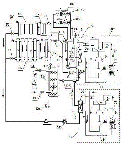
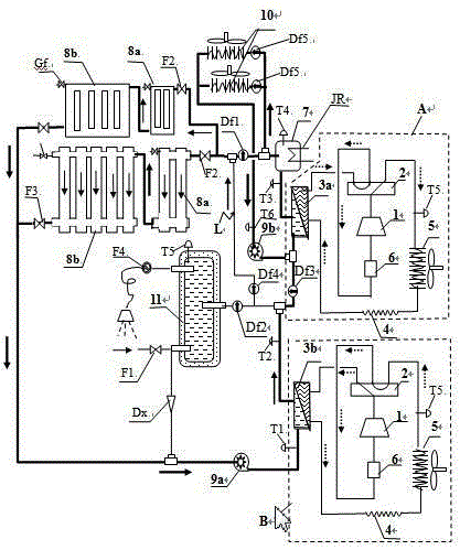
[0036] The basic structure of the heat pump heating, air conditioning, hot water and dehumidification combination system of the present invention is as follows: figure 1 As shown, the system includes: two heat pump refrigeration systems, A system and B system in the dotted box; front-stage hot water radiator 8a and rear-stage hot water radiator 8b, water-air heat exchanger 10, auxiliary electric water heater 7. Hot water tank 11, circulating water pump 9a, solenoid valve, manual valve, temperature sensor, pressure sensor, electrical control system; heat pump refrigeration system includes: compressor 1, four-way valve 2, water heat exchangers 3a and 3b, wind Heat exchanger 5, throttling device 4, gas-liquid separator 6, temperature and pressure sensors; the air heat exchanger has a fan; the exhaust port of the compressor is connected to the inlet port of the four-way valve, and the inlet port of the four-way valve There are three interfaces on the opposite side of the air port...
Embodiment 2
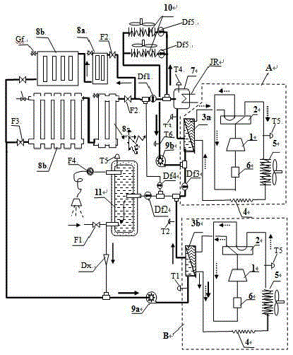
[0044] Example 2 , Image 6 It is the basic structural diagram of Embodiment 2 of the heat pump heating, air conditioning, hot water and dehumidification combination system of the present invention. Embodiment 2 and Embodiment 1 except that the connection mode between the water-air heat exchanger and the water heating radiator has been changed and the water heating radiator has been canceled. Except for the water heating radiator of the first stage, other systems are connected in the same way; Embodiment 2 The water-air heat exchanger and the water heating radiator operate in series, replacing the front-stage water heating radiator of the combined water heating radiator; the pipeline of the alternative The connection method is: the water outlet main pipe of the water-air heat exchanger 10 is divided into two branches. The sixth solenoid valve Df6 and the second circulating water pump 9b are installed on the water pipe; the second outlet pipe is connected to the main water ...
PUM
 Abstract
Description
Claims
Application Information