Fast factorized back-projection SAR self-focusing method

A factorization and back-projection technology, applied in the field of radar, can solve problems such as motion errors

Active Publication Date: 2017-06-06
UNIV OF ELECTRONIC SCI & TECH OF CHINA
View PDF4 Cites 17 Cited by
  • Summary
  • Abstract
  • Description
  • Claims
  • Application Information

AI Technical Summary

Problems solved by technology

[0005] The purpose of the present invention is to solve the problem of motion error compensation in the prior art for the fast factorization

Method used


Image

  • Fast factorized back-projection SAR self-focusing method
  • Fast factorized back-projection SAR self-focusing method
  • Fast factorized back-projection SAR self-focusing method

Examples


Embodiment Construction

[0080] Embodiments of the present invention will be further described below in conjunction with the accompanying drawings.

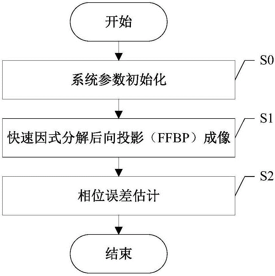
[0081] The present invention provides a fast factorization back-projection SAR self-focusing method based on maximum image sharpness, such as figure 1 shown, including the following steps:

[0082] S0, system parameter initialization.

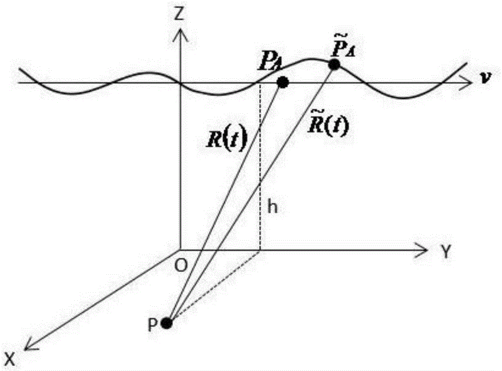
[0083] Use the scene reference target point O=[0 0 0] T Establish a coordinate system for the origin, and record the position of any pixel in the scene as P=[x y 0] T , the ideal position of the radar platform is recorded as P A =[0 vt h] T .

[0084] Among them, v is the ideal flight speed of the carrier aircraft along the y-axis, h is the ideal flight height of the carrier aircraft along the y-axis, and t is the azimuth slow time.

[0085] The ideal instantaneous distance between any pixel point and the radar platform is recorded as R(t)=||P-P A ||; When there is a deviation in the flight trajectory, the actual p...


PUM


Abstract

The invention discloses a fast factorized back-projection SAR self-focusing method. A phase error optimization model is established by combining a fast factorized back-projection imaging algorithm (FFBP), and the optimization model is solved by using a coordinate descent method and a secant method so that the problem of phase error compensation can be effectively solved. Compared with the methods in the prior art, the phase error can be more accurately estimated and a great focusing SAR image can be obtained so that the problems of high computational burden, low accuracy and low adaptability of the existing FFBP self-focusing method can be solved, and accurate motion error estimation and great focusing combining FFBP imaging can be realized.

Description

technical field [0001] The invention belongs to the technical field of radar, in particular to the design of a fast factorization back projection SAR self-focusing method based on maximum image sharpness. Background technique [0002] Synthetic Aperture Radar (SAR) is a high-resolution imaging radar. Compared with optical sensors, SAR has the unique advantage of being able to work around the clock. With the development and improvement of SAR technology, its resolution is getting higher and higher. At present, it is close to or surpasses the resolution of optical imaging, so it is widely used in the fields of earth remote sensing, ocean research, resource exploration, disaster prediction and military reconnaissance. . [0003] The fast factorization back projection (FFBP) imaging method based on time domain has no approximation processing, has high-precision imaging capability and good phase preservation characteristics, and is suitable for almost all SAR systems, including ...

Claims


Application Information

Patent Timeline
IPC IPC(8): G01S13/90G01S7/40
CPCG01S7/40G01S13/904G01S13/9017G01S13/9019
Inventor 武俊杰李云莉蒲巍杨建宇黄钰林杨海光杨晓波杜科郭德明
Owner UNIV OF ELECTRONIC SCI & TECH OF CHINA
Why Eureka
Try Eureka