Flue gas desulfurization, denitration and dust removal device and method

A technology for desulfurization, denitrification, and dust removal devices, which is applied in separation methods, chemical instruments and methods, and dispersed particle separation, etc., can solve problems such as inability to remove catalysts, inability to process adjustments, and reduce the effect of flue gas dust removal, so as to facilitate large-scale promotion. Application, simple operation, good processing effect

Inactive Publication Date: 2017-06-09
BC P INC CHINA NAT PETROLEUM CORP +1
View PDF1 Cites 0 Cited by
  • Summary
  • Abstract
  • Description
  • Claims
  • Application Information

AI Technical Summary

Problems solved by technology

[0005] The flue gas desulfurization, denitrification and dust removal devices provided by the prior art cannot remove the catalyst remaining in the flue gas, and cannot adjust the process at any time according to the change of the dust content in the flue gas, which reduces the dust removal effect of the flue gas

Method used


Image

  • Flue gas desulfurization, denitration and dust removal device and method
  • Flue gas desulfurization, denitration and dust removal device and method

Examples


Embodiment 1

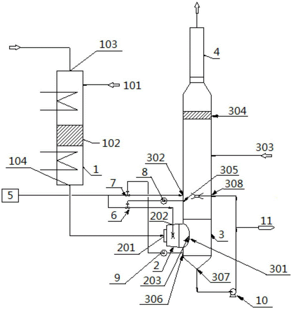
[0071] This embodiment provides a flue gas desulfurization, denitrification and dust removal device, which includes: a waste heat boiler 1 , a cooler 2 , a washing tower 3 , a chimney 4 , a water inlet 5 , a temperature control valve 6 , and a liquid level control valve 7 .

[0072] The upper part of the waste heat boiler 1 is provided with an ammonia gas inlet 101, the middle part is provided with a denitrification reactor 102, the top is provided with a first flue gas inlet 103, and the bottom part is provided with a flue gas outlet 104; the denitrification catalyst loaded in the denitrification reactor 102 is Topsoe's DNX series Catalyst, BASF O4-85 catalyst, FN-2 catalyst of Fuyan Research Institute.

[0073] The lower part of the washing tower 3 is provided with a second flue gas inlet 301, a water inlet 302, and a liquid level detection port 306. The middle part is provided with a lye inlet 303 and a temperature detection port 305. The upper part is provided with a deliqu...

Embodiment 2

[0079] In this embodiment, the device provided in Embodiment 1 is used for desulfurization, denitrification and dust removal treatment, which specifically includes the following steps:

[0080] The flue gas is introduced into the waste heat boiler 1, and when the temperature in the waste heat boiler 1 is between 340-380°C, the ammonia gas with an ammonia volume concentration of 3-5% is passed into the waste heat boiler 1 to mix the flue gas with the ammonia gas, Then, the flue gas is denitrated by the denitrification reactor 102 in the waste heat boiler 1 to obtain denitrification flue gas.

[0081] Make the denitrification flue gas enter the cooler 2, enter the washing tower 3 after cooling, and add NaOH solution with a mass concentration of 10% to the washing tower 3 at the same time, and carry out desulfurization and dust removal treatment on the denitrification flue gas through the NaOH solution. The level control valve keeps the liquid level in the washing tower 3 stable ...


PUM


Abstract

The invention discloses a flue gas desulfurization, denitration and dust removal device and method and belongs to the field of flue gas treatment by catalytic cracking. The device comprises a residual heat boiler, a cooler, a washing tower, a chimney, a water feeder, a temperature control valve and a liquid level control valve. A first flue gas inlet is formed in the top of the residual heat boiler and an ammonia gas inlet is formed in the upper part of the residual heat boiler; a denitration reactor is arranged in the middle of the residual heat boiler; a flue gas outlet is formed in the bottom of the residual heat boiler. A second flue gas inlet and a water inlet are formed in the lower part of the washing tower; an alkali liquid inlet is formed in the middle of the washing tower; a liquid and dust remover is arranged at the upper part of the washing tower and a chimney connector is arranged at the top of the washing tower. The cooler is provided with a gas phase inlet, a liquid phase inlet and an outlet. The flue gas outlet on the residual heat boiler, the gas phase inlet and the outlet of the cooler, the second flue gas inlet and the chimney connector of the washing tower, and the chimney are connected in sequence. The temperature control valve is arranged on a pipeline between the water feeder and the liquid phase inlet of the cooler; the liquid level control valve is arranged on a pipeline between the water feeder and the water inlet of the washing tower. The device disclosed by the invention can be used for carrying out desulfurization, denitration and dust removal treatment on flue gas from an FCC device.

Description

technical field [0001] The invention relates to the field of catalytic cracking flue gas treatment, in particular to a flue gas desulfurization, denitration and dust removal device and method. Background technique [0002] In the process of catalytic cracking of heavy oil using a fluidized catalytic cracking unit (ie FCC unit), it is necessary to burn the coke adsorbed on the catalyst to regenerate the catalyst. During the burning process, the sulfur, nitrogen and other substances contained in the coke will be released, and together with dust particles such as ash and coal, they will form flue gas and be discharged into the atmosphere. Discharging flue gas directly into the air will cause serious air pollution. Therefore, in order to protect the environment, it is necessary to desulfurize, denitrify and dedust the flue gas before discharging it. Therefore, it is very necessary to provide a flue gas desulfurization, denitrification and dust removal device. [0003] The flu...

Claims


Application Information

Patent Timeline
Patent Type & Authority Applications(China)
IPC IPC(8): B01D53/76B01D53/56B01D53/78B01D53/50
Inventor 杨玉臣阚伟孙朝辉李山明赵丽娟李瑛玉
Owner BC P INC CHINA NAT PETROLEUM CORP
Why Eureka
Try Eureka