
Method for attaching carbon-coated copper foil in organic electroluminesence display

An electro-laser, copper foil technology, applied in chemical instruments and methods, layered products, lamination devices, etc., can solve the problems of easy attachment and unevenness, easy existence of air bubbles, lamination deformation of carbon-coated copper foil, etc.

Active Publication Date: 2017-06-09
SUZHOU JIERUISI INTELLIGENT TECH CO LTD
View PDF3 Cites 2 Cited by
  • Summary
  • Abstract
  • Description
  • Claims
  • Application Information

AI Technical Summary

Problems solved by technology

[0003] Carbon-coated copper foil sometimes needs to be attached to a hard board in the production of electronic products. The thickness of carbon-coated copper foil is very thin and flexible. Compared with the board, it has higher hardness. Flexible copper foil and hard Direct manual attachment between the pasting boards is easy to be uneven, and air bubbles are likely to exist in the middle of the carbon-coated copper foil and the pasting board, and the carbon-coated copper foil may have overlapping deformation
For boards with curved surfaces, it is more difficult to attach, and the attachment effect is more difficult to control

Method used


Image

  • Method for attaching carbon-coated copper foil in organic electroluminesence display
  • Method for attaching carbon-coated copper foil in organic electroluminesence display
  • Method for attaching carbon-coated copper foil in organic electroluminesence display

Examples


Embodiment Construction

[0029] Below in conjunction with specific embodiment, content of the present invention is described in further detail:

[0030] In order to achieve the purpose of the present invention, in some embodiments of the present invention, a method for attaching carbon-coated copper foil in an organic electric laser display:

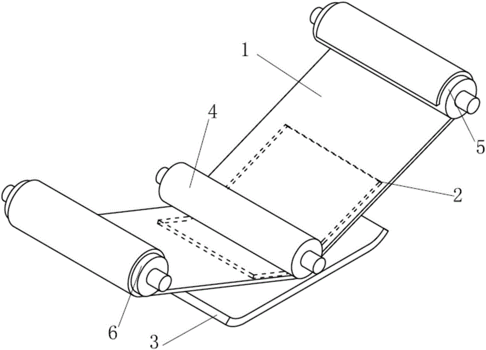
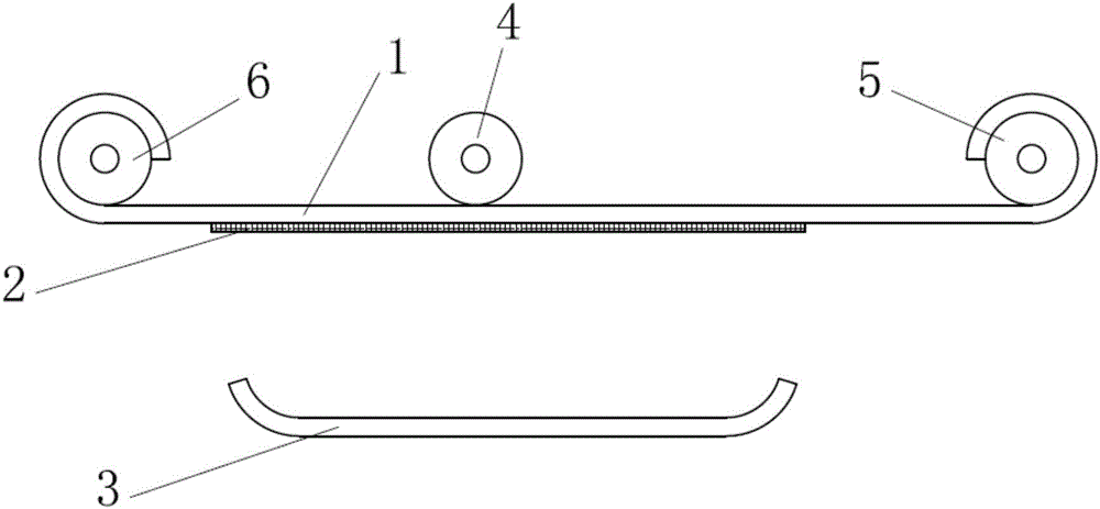
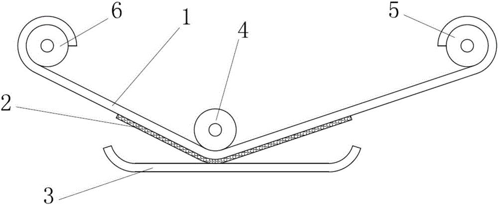
[0031] figure 2 It shows a front view of the pressing roller in an unpressed state in one embodiment of the present invention. The intermediate belt 1 is connected between the first roller 5 and the second roller 6, and the intermediate belt 1 can move along the left and right direction in the figure as the first roller 5 or the second roller 6 is wound. The lower surface is attached to the upper surface of the carbon-coated copper foil 2, the middle belt 1 and the carbon-coated copper foil 2 are in a natural and straight state, and the sticking plate 3 is fixed below the carbon-coated copper foil 2 with a certain distance between them. Since the carbon-coate...


PUM


Abstract

The invention discloses a method for attaching a carbon-coated copper foil in an organic electroluminesence display. The method comprises the following steps: attaching the upper surface of a carbon-coated copper foil to the lower surface of a middle strip; pressing a position corresponding to the carbon-coated copper foil, of the middle strip; enabling the lower surface of the carbon-coated copper foil to be in contact with the upper surface of an attaching plate, and rolling the middle strip; transferring and attaching the carbon-coated copper foil to the upper surface of the attaching plate from the lower surface of the middle strip. The lower surface of the middle strip has viscosity, and the viscosity is less than those of the lower surface of the carbon-coated copper foil and the upper surface of the attaching plate, so that the carbon-coated copper foil can be transferred to the attaching plate. The middle strip has ductility, the surface of the middle strip can be prolonged when the pressing rollers presses down, the carbon-coated copper foil attached to the surface of the middle strip is tightened and flattened because of certain tensile force, then the attaching flatness can be improved, the middle strip has elastic and capillary pores perpendicular to the direction of the surface of the middle strip, soft force is needed when the carbon-coated copper foil is attached, bubbles can be avoided, the attaching flatness of the carbon-coated copper foil can be improved, the attaching efficiency can be improved, and the method can be applied to the field of curved surface attachment.

Description

technical field [0001] The invention relates to a sticking method, in particular to a sticking method of a carbon-coated copper foil in an organic electric laser display. Background technique [0002] Carbon-coated copper foil has a unique grain orientation that conducts heat evenly in two directions, and its lamellar structure adapts well to any surface. Conduct heat conduction through high thermal conductivity, and then convert heat energy into infrared radio frequency through high thermal radiation performance of carbon atoms to transfer heat dissipation performance. It has high thermal conductivity and high heat radiation efficiency. It is often used in the heat dissipation field of electronic products. [0003] Carbon-coated copper foil sometimes needs to be attached to a hard board in the production of electronic products. The thickness of carbon-coated copper foil is very thin and flexible. Compared with the board, it has higher hardness. Flexible copper foil and ha...

Claims


Application Information

Patent Timeline
IPC IPC(8): B32B37/10
CPCB32B37/10
Inventor 文二龙潘其林
Owner SUZHOU JIERUISI INTELLIGENT TECH CO LTD
Learn More