Environmentally friendly water-waving washing machine and water draining method thereof
A water-saving washing machine and an environment-friendly technology, applied in the field of washing machines, can solve the problems of many sealing links, secondary pollution of clothes, and sealing failure, etc., and achieve the effects of less sealing links, prevention of secondary pollution, and good reliability.
- Summary
- Abstract
- Description
- Claims
- Application Information
AI Technical Summary
Problems solved by technology
Method used
Image
Examples
Embodiment 1
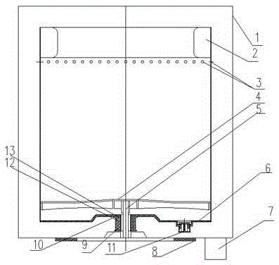
[0029] Such as figure 1 As shown, the present invention provides an environment-friendly water-saving washing machine, which includes an inner tub 2 and an outer tub 1, the inner tub 2 is concentrically installed in the outer tub 1, the inner tub 2 is an integral water storage bucket, and the bottom of the inner tub 2 is connected with an inner tub Flange 6, the inner barrel flange 6 is installed on the upper shaft sleeve 12 of the deceleration clutch, and a sealing gasket 13 is arranged between the inner barrel flange 6 and the upper shaft sleeve 12.
[0030] Further, the uppermost end of the inner barrel 2 is provided with a balance ring, and the lower end of the inner barrel next to the balance ring is provided with a circle of radial water throwing holes 3 , and the bottom of the outer barrel 1 is provided with a drain port 7 .
[0031] Further, the bottom of the inner tub 2 is provided with a drain valve.
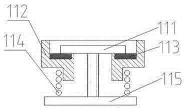
[0032] Such as figure 2 As shown, the drain valve is a normall...
Embodiment 2
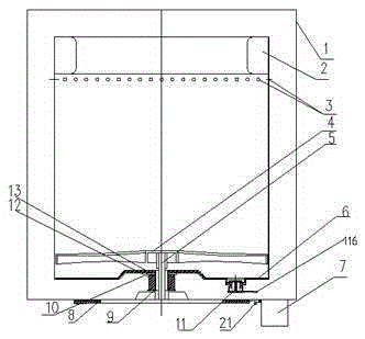
[0038] Others are the same as in Example 1, and the difference in the scheme provided in this example is: in combination image 3 , Figure 4 In this embodiment, the ring-shaped electromagnet 8 in Embodiment 1 is removed, and a circle of a group of electromagnets 8 arranged in a ring by a single electromagnet is arranged on the original position of the ring-shaped electromagnet 8. The group electromagnet 8 is at the bottom of the outer cylinder right below the normally closed check valve 11 .
[0039] Further, a group of electromagnetic switches 21 are arranged in a circular position on the bottom of the outer cylinder of the group of electromagnets 8, and the electromagnetic switches 21 control the energization status of a single electromagnet 8 correspondingly. There is an electromagnetic switch contact block 21 at the corresponding position directly above the electromagnetic switch 21 described in 21. The electromagnetic switch contact block 21 is a magnetic material, and th...
Embodiment 3
[0043] Such as Figure 5 As shown, the others are the same as in Embodiment 1. In this embodiment, a shift fork 18 is provided on the outer bottom of the inner barrel 1, and the shift fork 18 is movably connected with the shift fork fulcrum 17 installed on the inner barrel 1. The manipulator is linked with the shift fork 18, the manipulator is not in contact with the fork 18, and the manipulator and the shift fork 18 indirectly control the opening and closing of the drain valve through the action of non-contact force. The manipulator is an electromagnet 8, one end of the shift fork 18 is in contact with the valve cover 115, and the corresponding position below the other end of the shift fork 18 is an electromagnet 8, and the electromagnet 8 is a ring-shaped electromagnetic Iron 8, the electromagnet 8 is arranged at the outer bottom of the outer cylinder 2, and the ring-shaped electromagnet 8 indirectly acts on the valve cover to open the normally closed one-way valve 11 throug...
PUM
 Abstract
Description
Claims
Application Information
 - R&D
- Intellectual Property
- Life Sciences
- Materials
- Tech Scout
- Unparalleled Data Quality
- Higher Quality Content
- 60% Fewer Hallucinations
Browse by: Latest US Patents, China's latest patents, Technical Efficacy Thesaurus, Application Domain, Technology Topic, Popular Technical Reports.
© 2025 PatSnap. All rights reserved.Legal|Privacy policy|Modern Slavery Act Transparency Statement|Sitemap|About US| Contact US: help@patsnap.com


