Overall ventilation system of microwave oven

A ventilation system and microwave oven technology, applied in the field of microwave ovens, can solve the problems of high cost of parts, bulky air duct structure, and low production efficiency, and achieve the effects of reducing cost input, expanding application range, and improving production efficiency

Pending Publication Date: 2017-06-09
青岛兴邦烤箱有限公司
View PDF4 Cites 1 Cited by
  • Summary
  • Abstract
  • Description
  • Claims
  • Application Information

AI Technical Summary

Problems solved by technology

This air duct structure has the following disadvantages: 1) The inlet and outlet air ducts of this air duct structure will interfere with each other, and the heat dissipation and smoke exhaust effect is not good; 2) The air duct structure is heavy and bulky; 3) The mold investment is large; 4) Low production efficiency; 5) Complicated assembly; 6) High cost of parts; 7) Loud noise

Method used


Image

  • Overall ventilation system of microwave oven
  • Overall ventilation system of microwave oven
  • Overall ventilation system of microwave oven

Examples


Embodiment Construction

[0055] Specific embodiments of the present invention will be described below in conjunction with the accompanying drawings.

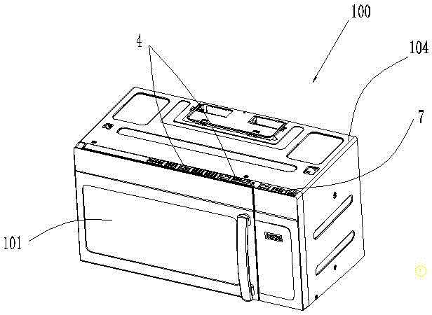
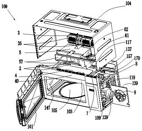
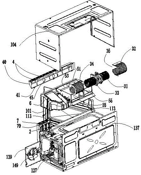
[0056] like Figure 1 to Figure 3 As shown, a microwave oven 100 with a microwave oven integrated ventilation system according to a specific embodiment of the present invention includes a door body 101, a front panel 103, a casing 104, a cooking cavity 105, a cavity wall surrounding and forming a cooking chamber, and a cavity wall located in the cooking cavity 105. Mechanical room 109 on the right. The cavity walls include a top cavity wall or top plate 117, a bottom cavity wall or bottom plate 127, a rear cavity wall or rear plate 137, a left cavity wall or left plate 147 and a right cavity wall or right plate 157. Components such as a magnetron 119 and a transformer 129 are installed in the mechanical chamber 109 .

[0057] Figure 2 to Figure 8 A microwave oven integrated ventilation system according to a specific embodiment of the present invent...


PUM


Abstract

The invention relates to an overall ventilation system of a microwave oven. The overall ventilation system comprises vent holes, a throughflow fan, exhaust grids, a vapor flue, a heat radiation flue, air inlet grids, a heat radiation opening and a heat radiation fan, wherein the exhaust grids are used for providing exhaust holes; the heat radiation flue consists of an air inlet flue and an air exhaust flue; the air inlet grids are used for providing air holes; the heat radiation flue is integrally formed with the vapor channel; the exhaust flue is positioned between the air inlet flue and the vapor channel; the exhaust flue and the vapor channel are both communicated with the exhaust holes; the air inlet flue is communicated with the air inlet holes; the throughflow fan is used for sucking vapor from a cooking cavity through the vent holes and used for discharging the vapor outside the microwave oven; external air is introduced into a machine chamber from the air inlet holes, the air inlet channel and the heat radiation opening; hot air in the machine room is discharged outside the microwave oven from the heat radiation opening, the exhaust channel and the exhaust holes. As the vapor channel and the heat radiation channel are integrated, and the channels are separated, the overall ventilation system is relatively compact in structure, small in noise and high in exhaust air rate, and due to modularization of the channels, the overall ventilation system is universal.

Description

technical field [0001] The invention relates to the technical field of microwave ovens, in particular to an integrated ventilation system for microwave ovens. Background technique [0002] At present, the air ducts of OTR microwave ovens (hanging microwave ovens) on the market are open. Specifically, the assembled casing and air duct parts are used to form the inlet and outlet air ducts. There will be some gaps of different sizes between the casing and the air duct parts, causing other problems. This air duct structure has the following disadvantages: 1) The inlet and outlet air ducts of this air duct structure will interfere with each other, and the heat dissipation and smoke exhaust effect is not good; 2) The air duct structure is heavy and bulky; 3) The mold investment is large; 4) Low production efficiency; 5) Complicated assembly; 6) High cost of parts; 7) Loud noise. Contents of the invention [0003] In order to overcome the above, it will be beneficial for th...

Claims


Application Information

Patent Timeline
Patent Type & Authority Applications(China)
IPC IPC(8): F24C7/02F24C15/00
CPCH05B6/64F24C15/00
Inventor 唐春玉蒋雏燕钟海华刘连程郭宏业
Owner 青岛兴邦烤箱有限公司
Why Eureka
Try Eureka