
Three-phase unit characteristic point matching method, measuring method and three dimensional detection device

A feature point matching and feature point technology, which is applied in the field of optical and electronic measurement, can solve the problems of increasing application cost, many cameras, and affecting measurement accuracy.

Active Publication Date: 2017-06-09
BEIJING QINGYING MACHINE VISUAL TECH CO LTD
View PDF4 Cites 5 Cited by
  • Summary
  • Abstract
  • Description
  • Claims
  • Application Information

AI Technical Summary

Problems solved by technology

[0005] The four-camera planar array feature point matching method uses more cameras, which increases the application cost. At the same time, due to the number of cameras, it also increases the difficulty of processing and the complexity of calculation, which also affects the measurement accuracy.

Method used


Image

  • Three-phase unit characteristic point matching method, measuring method and three dimensional detection device
  • Three-phase unit characteristic point matching method, measuring method and three dimensional detection device
  • Three-phase unit characteristic point matching method, measuring method and three dimensional detection device

Examples


Embodiment 1

[0089] This embodiment relates to a method for matching feature points of a three-phase unit.

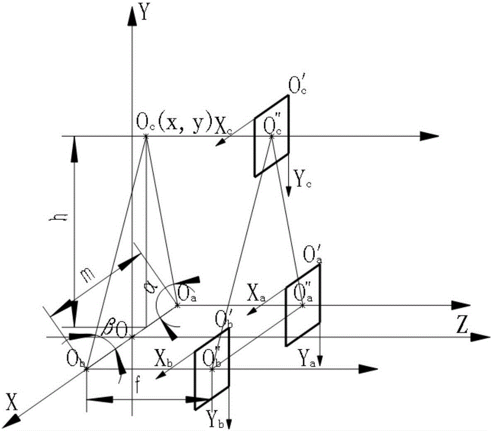
[0090] 1. Establish a three-dimensional measurement system and a three-dimensional coordinate system for the front image model of the plane three-camera unit.

[0091] In order to facilitate the description of the feature point matching method and measurement method of the planar three-camera group in the embodiment of the present invention, it is necessary to establish a planar three-camera group three-dimensional measurement system that meets the requirements and the three-dimensional coordinate system corresponding to the planar three-camera group three-dimensional measurement system. It is more convenient to apply the method of the embodiment of the present invention, use the forward projection model, and adopt the three-dimensional measurement system of the plane three-phase unit and the corresponding three-dimensional coordinate system established in the following manner:

[0...

Embodiment 2

[0154] This embodiment relates to a three-camera planar array feature point measurement method.

[0155] Include the following steps:

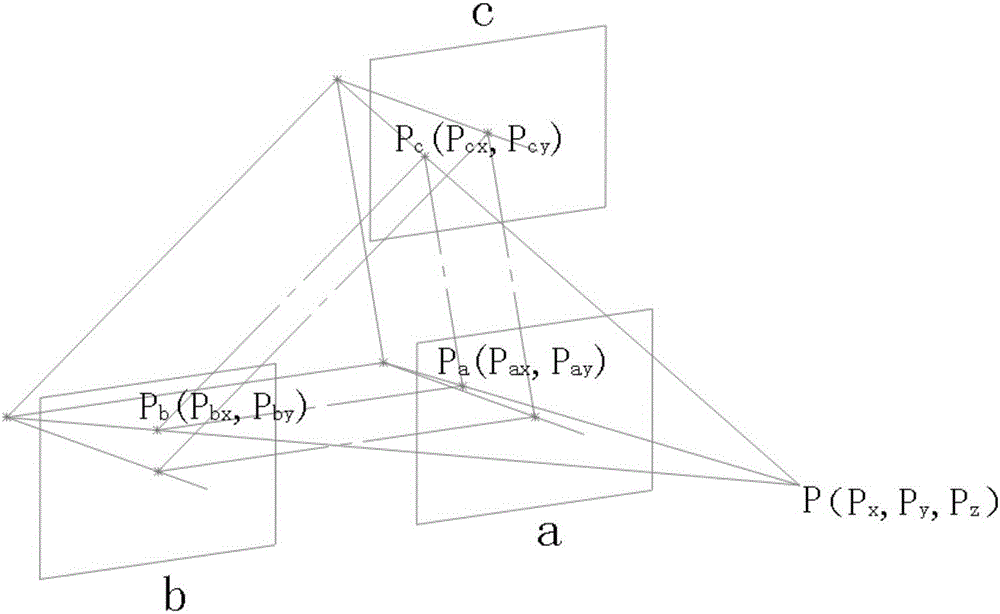
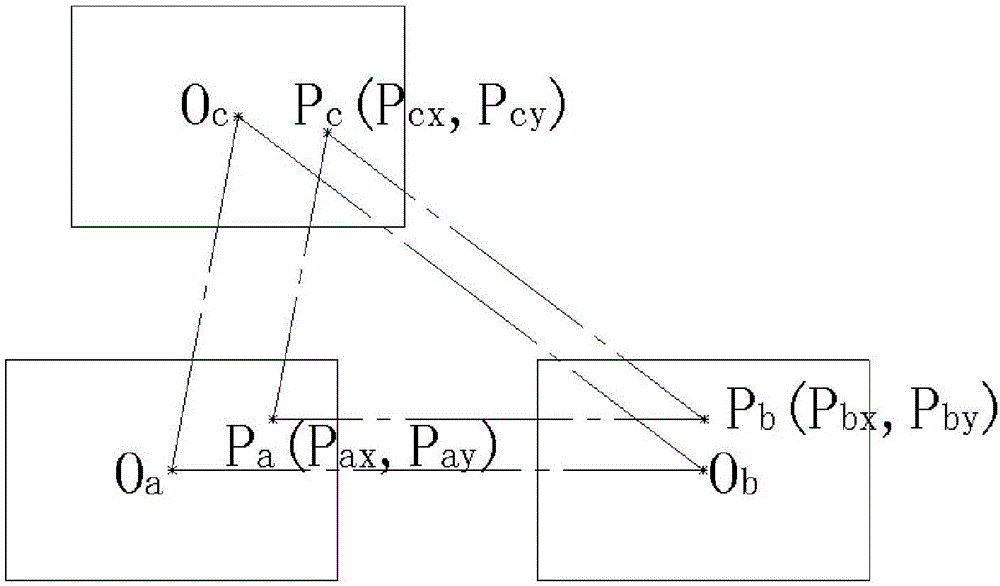
[0156] b1. After the image acquisition is completed, use the method adopted in embodiment 1 to find out the unique matching point group corresponding to all the feature points in the base image plane;

[0157] b2. According to the image coordinates of the unique matching point group obtained in step b1, calculate the spatial position coordinates of the viewpoint;

[0158] b3. According to the spatial position coordinates of the viewpoint obtained in step b2, form 3D point cloud data, establish a 3D point cloud graphic, and reproduce a 3D stereoscopic image.

[0159] Step b1 includes:

[0160] b11. Take one image plane in the horizontal image plane of a group of three-camera group as the base image plane, and for a feature point on the base image plane, find out the adjacent base image plane in the lateral direction according to the matching ...


PUM


Abstract

The invention relates to the optics electronic measurement technique field, and especially relates to a three-phase unit characteristic point matching method, a measuring method and a three dimensional detection device; the measuring method comprises the following steps: b1, collecting images, and finding a unique matching point set corresponding to all characteristic points in a base image plane; b2, calculating space position coordinates of viewed points according to the image coordinates of the unique matching point set obtained in step b1; b3, forming three dimensional point cloud data according to the viewed point space position coordinates obtained in step b2, building a three dimensional point cloud graph, and rebuilding a three dimensional stereo image. The advantages are that 1, the method and device can match the versatility and uniqueness of viewed points respectively imaging on three cameras; 2, the method can realize three dimensional measurement of the viewed object; 3, the method can fast realize three dimensional perception and measurement; 4, the method uses less cameras, thus reducing application cost.

Description

technical field [0001] The invention relates to the technical field of optical and electronic measurement, in particular to a method for matching feature points of a three-phase unit, a measurement method and a three-dimensional detection device. Background technique [0002] At present, three-dimensional stereo vision measurement generally adopts line laser light screenshot measurement technology or binocular measurement plus structured light illumination. The corresponding matching points are clarified in the imaging, the ambiguity of matching is reduced, and a definite and unique matching is realized. However, if the indication of line laser or structured light is canceled, binocular matching cannot avoid the ambiguity of multi-point matching, so that the measurement requirements cannot be met. At the same time, line laser or structured light can only be used for line laser or structured light imaging. Measurements limit the scope of application of this technology, and t...

Claims


Application Information

Patent Timeline
IPC IPC(8): G01B11/24
CPCG01B11/24
Inventor 曹亮周之琪尹兴龚婷
Owner BEIJING QINGYING MACHINE VISUAL TECH CO LTD
Learn More