Cast iron pipe anti-leakage layer mark detecting and smearing system

A technology of marking detection and anti-leakage layer, used in liquid/vacuum measurement for liquid tightness, jetting device, etc., can solve the problems of great impact on human health, high cost of type board, complicated installation of testing equipment, etc.

Inactive Publication Date: 2017-06-13
安庆牛力模具股份有限公司
View PDF9 Cites 5 Cited by
  • Summary
  • Abstract
  • Description
  • Claims
  • Application Information

AI Technical Summary

Problems solved by technology

[0002] At present, in domestic centrifugal cast iron pipe production plants, the marks on the outer surface of the finished ductile cast iron pipe are basically spray-printed manually with hand-held spray guns and letter boards. The labor intensity of the workers is high, which affects the production rhythm, and the atomized paint during the operation And thinners have a great impact on human health. In terms of quality, hand-printed marks (marks) often have problems such as virtual characters, white edges, and unclear printing. The overall appearance quality is affected; in terms of cost, there are many type plates used for printing, especially for export contracts, and the cost of type plates is relatively high
[0003] Moreover, after the pipeline is processed, it is also necessary to perform leak detection on the pipeline to prevent tiny leaks on the pipeline. The traditional detection equipment is complicated to install and has low efficiency.

Method used


Image

  • Cast iron pipe anti-leakage layer mark detecting and smearing system

Examples


Embodiment Construction

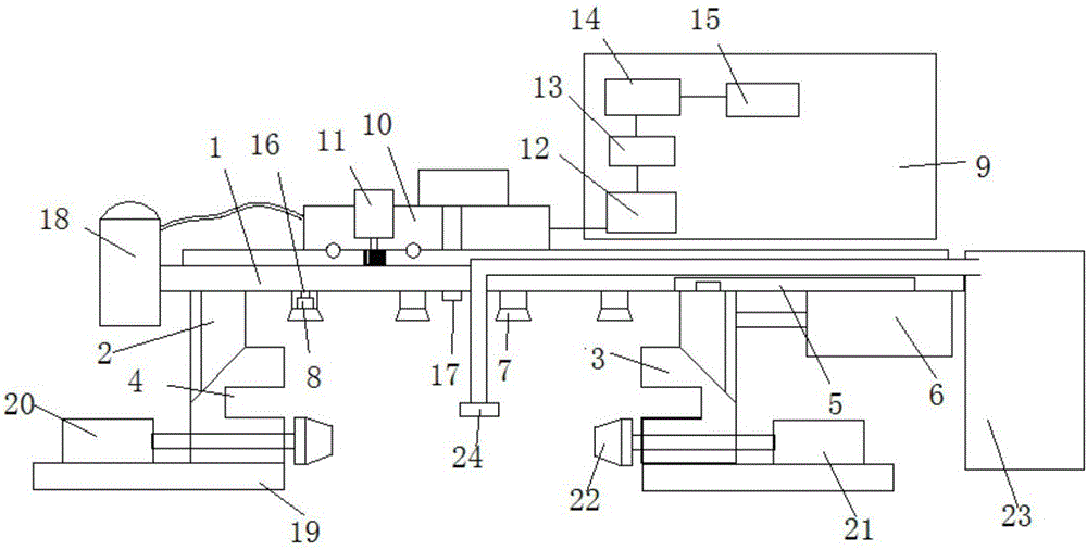
[0010] Referring to the accompanying drawings, a cast iron pipe leak-proof layer marking detection and smearing system includes a beam plate 1, left and right pipe clamps 2, 3, and the lower surface of the beam plate 1 is provided with left and right pipe clamps 2, 3 3. A bottom plate 19 is provided on the side walls of the left and right pipe clamps 2 and 3, a hydraulic cylinder 20 is fixedly installed on the left bottom plate, and a rotating motor 21 is provided on the right pipe clamp. The piston rod 20 and the shaft end of the motor 21 are respectively provided with a top block 22, the right end of the beam plate is provided with an asphalt tank 23, the asphalt tank 23 is connected with a spray pipe 24, the left and right pipe clamps 2, The side wall of 3 is provided with a bayonet 4, the upper end of the right pipe clamp 3 is slidably clamped in the chute 5, the side wall of the right pipe clamp 3 is connected with a cylinder 6, and the cylinder 6 is fixed on the beam. Th...


PUM


Abstract

The invention discloses a cast iron pipe anti-leakage layer mark detecting and smearing system which comprises a cross beam plate, a left pipe clamp and a right pipe clamp. The cast iron pipe anti-leakage layer mark detecting and smearing system is characterized in that the left pipe clamp and the right pipe clamp are arranged on the lower surface of the cross beam plate, clamping openings are formed in the side wall of the left pipe clamp and the side wall of the right pipe clamp, and the upper end of the right pipe clamp is clamped in a sliding groove in a sliding manner; and the side wall of the right pipe clamp is connected with an air cylinder, the air cylinder is fixed to the lower surface of the cross beam plate, a plurality of collecting covers are arranged at the positions, between the left pipe clamp and the right pipe clamp, of the lower surface of the cross beam plate, and sound signal collectors are fixedly mounted in the collecting covers. The cast iron pipe anti-leakage layer mark detecting and smearing system is high in detection efficiency, a bottom plate is arranged on the pipe clamps, a hydraulic cylinder and a motor are arranged on the bottom plate, cast iron pipe clamping and rotating are facilitated, and asphalt can be conveniently and evenly sprayed to the outer wall of a cast iron pipe; and leakage detection marking is completed at a time, and mounting and use are stable and firm.

Description

technical field [0001] The invention relates to a processing equipment of cast iron pipes, in particular to a system for detecting and smearing marks of a leak-proof layer of cast iron pipes. Background technique [0002] At present, in the domestic centrifugal cast iron pipe production plants, the outer surface marking of the finished ductile cast iron pipe is basically spray-printed manually with a hand-held spray gun and a word plate. The labor intensity of the workers is high, which affects the production rhythm, and the paint atomized during the operation is sprayed. and thinner materials have a great impact on human health. In terms of quality, hand-printed logos (marks) often have problems such as virtual characters, white borders, and unclear printing, especially for small-caliber tubes. The overall appearance quality is affected; in terms of cost, the fonts used for jet printing, especially the export contracts, are more expensive, and the cost of the fonts is high....

Claims


Application Information

Patent Timeline
IPC IPC(8): B05B13/02G01M3/02
CPCB05B13/0207B05B13/0278G01M3/02
Inventor 严冬祥
Owner 安庆牛力模具股份有限公司
Why Eureka
Try Eureka