
Method and apparatus for locating underground cast iron pipe joints

a technology of underground cast iron pipes and joints, applied in the direction of material magnetic variables, reradiation, instruments, etc., can solve the problems of inability to accurately locate, inability to use and apply these types of devices, and large number of false positive signals, etc., to achieve accurate locating

Active Publication Date: 2008-12-16
GAS TECH INST
View PDF8 Cites 11 Cited by
  • Summary
  • Abstract
  • Description
  • Claims
  • Application Information

AI Technical Summary

Benefits of technology

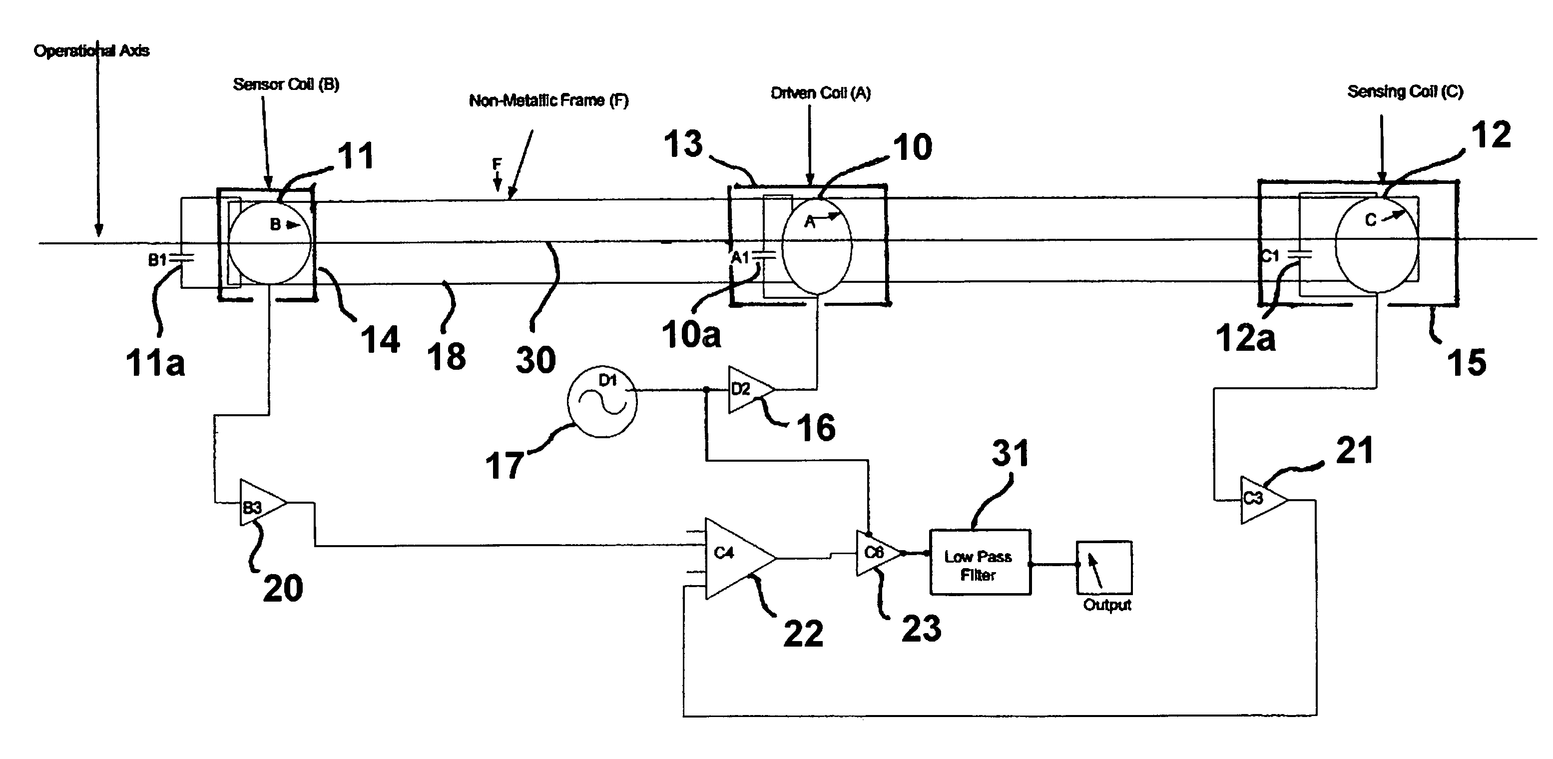
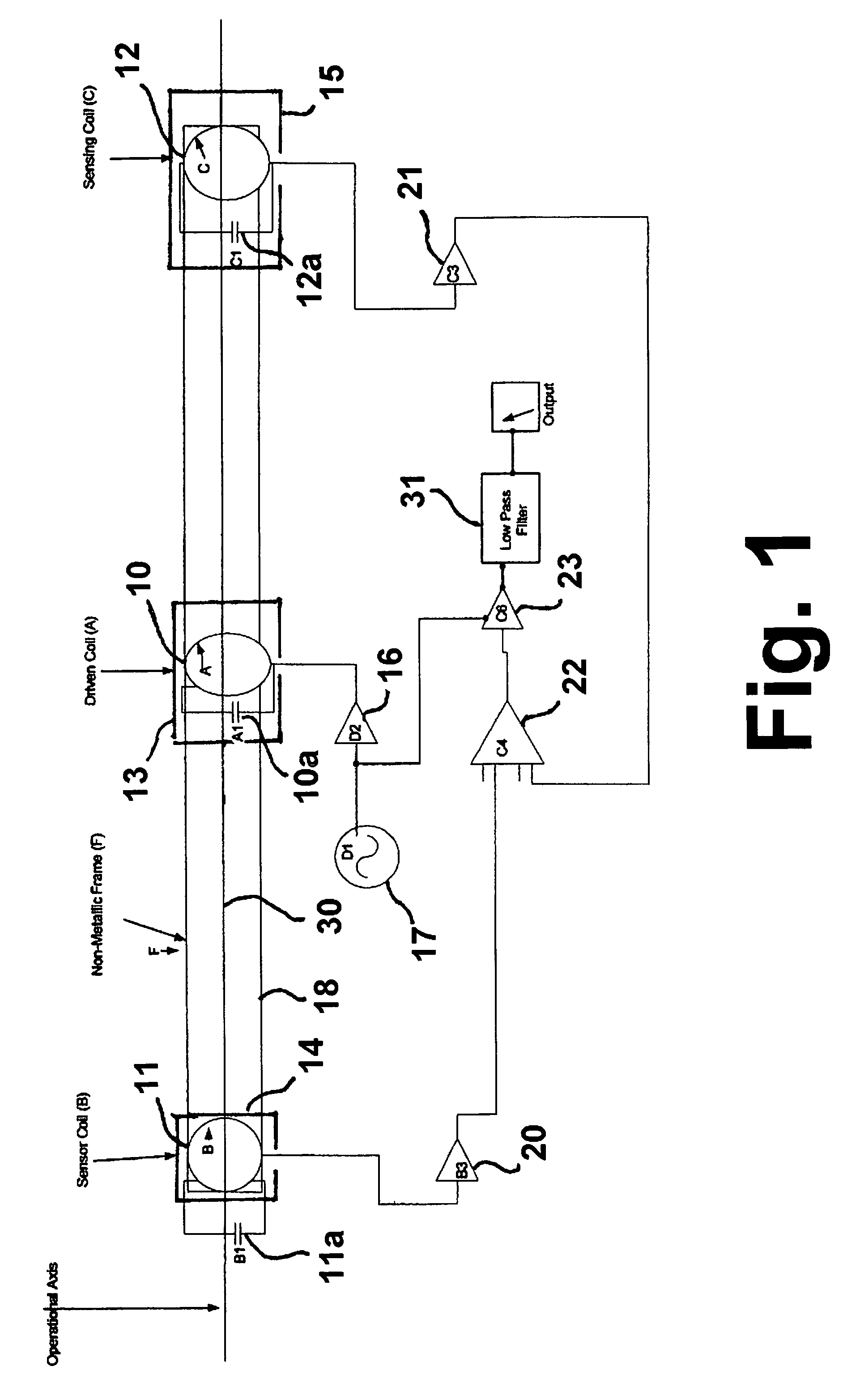
The invention is a method and apparatus for accurately locating underground cast iron pipes without excavation. It uses an electrically driven resonant coil to generate an alternating magnetic field and two resonant sensor coils with independent magnetic reluctance circuits to measure the changes in magnetic reluctance caused by the presence of ferromagnetic objects, such as cast iron pipe joints. The apparatus can detect ferromagnetic materials in the vicinity and measure the magnetic reluctance while moving the coils to locate the underground object. The technical effects of this invention are improved accuracy and efficiency in locating underground cast iron pipes without excavation.

Problems solved by technology

With time, problems generally develop which cause fluid leakage.
Technologies have been developed to seal these joints; however, to make the repairs requires excavation of the pipe.
However, these devices are also sensitive to variations in the soil, resulting in numerous false positive signals.
However, the requirement of mutually coupled coils inhibits the use and application of these types of devices.
These types of devices are very sensitive to slight jarring or impact, which may cause coil movement, rendering the device inaccurate.
Although, as evidenced by the above referenced U.S. patents, devices exist for locating buried pipe, none of these known devices is able to detect buried pipe joints or other buried pipeline features.

Method used


Image

  • Method and apparatus for locating underground cast iron pipe joints
  • Method and apparatus for locating underground cast iron pipe joints
  • Method and apparatus for locating underground cast iron pipe joints

Examples


example

[0034]A laboratory version of the apparatus of this invention was constructed using 83 kHz coils 8 inches in diameter. Aluminum foil was used as the electrostatic shielding on the coils. A 1 MHz crystal oscillator and a divide by 6 counter were used to drive two D-edge flip-flops. The output of the flip-flop circuits produced 83 kHz square waves with 0, 90, 180, and 270-degree phase shifts. The zero degree signal was used to trigger a logic FET used to drive the electrically driven resonant coil. The 0, 90, 180 and 270 degree phase signals were tried as inputs to the detector circuits. The signal from each of the resonant sensor coils 11, 12 were sent through high impedance voltage following amplifiers. The outputs of the amplifiers were connected to the inputs of a differential input instrumentation amplifier. The output of the instrumentation amplifier was further amplified and sent to demodulator / phase detector circuits. Two circuits, a balanced demodulator and a phase detector, ...


PUM


Abstract

An apparatus for locating underground cast iron pipe joints having an electrically driven resonant coil generating an alternating magnetic field and two resonant sensor coils disposed within the alternating magnetic field, each of the resonant sensor coils having an independent magnetic reluctance circuit. A device is provided for comparing electrical currents induced in each of the resonant sensor coils and a device is provided for indicating a relative magnitude of the electrical currents.

Description

BACKGROUND OF THE INVENTION[0001]1. Field of the Invention[0002]This invention, in general, relates to a method and apparatus for locating hidden ferromagnetic objects. More particularly, this invention relates to a method and apparatus for locating underground ferromagnetic objects without excavation. More particularly yet, this invention relates to a method and apparatus for locating underground cast iron pipes and cast iron pipe joints employed in underground fluid distribution systems, such as natural gas pipelines.[0003]2. Description of Related Art[0004]Many water and gas utilities have distribution pipelines constructed of cast iron. With time, problems generally develop which cause fluid leakage. For example, in the case of gas utilities, seepage of gas from the bell and spigot joints connecting the pipe sections can occur. Technologies have been developed to seal these joints; however, to make the repairs requires excavation of the pipe. Thus, the ability to accurately loca...

Claims


Application Information

Patent Timeline
Patent Type & Authority Patents(United States)
IPC IPC(8): G01V3/11
CPCG01N27/72
Inventor MCCARTY, JOE W.
Owner GAS TECH INST
Learn More