
Adjustable nozzle assembly for 3d printer

A technology for 3D printers and nozzle components, applied in the field of 3D printing, can solve problems such as inability to effectively control the printing speed of 3D printers, wire blockage, and wire feeding difficulties, and achieve the effects of increasing heat insulation, improving use efficiency, and good heat dissipation

Active Publication Date: 2019-05-24
山东爱舒乐卫生用品有限责任公司
View PDF6 Cites 0 Cited by
  • Summary
  • Abstract
  • Description
  • Claims
  • Application Information

AI Technical Summary

Problems solved by technology

At present, 3D printers based on FDM technology often encounter the problem of blockage caused by wire expansion during use. The main reason is that the plastic wire melts at the hot end of the nozzle after being heated. The upward transmission causes the wire above the hot end to expand, and the wire expands to produce a huge friction force with the inner lining, causing the problem of difficult wire feeding, and the inner diameter section shape of the extrusion nozzle of the conventional 3D printer print head is only a fixed circle. The volume of the nozzle spraying wire per unit time is constant
Due to the non-adjustable cross-sectional area of ​​the inner diameter of the nozzle, the printing speed of the 3D printer cannot be effectively controlled. However, different printing speeds are required for different printing purposes and different printing areas.

Method used


Image

  • Adjustable nozzle assembly for 3d printer
  • Adjustable nozzle assembly for 3d printer
  • Adjustable nozzle assembly for 3d printer

Examples


Embodiment Construction

[0036] The present invention will be further described in detail below in conjunction with the accompanying drawings, so that those skilled in the art can implement it with reference to the description.

[0037] It should be understood that terms such as "having", "comprising" and "including" as used herein do not entail the presence or addition of one or more other elements or combinations thereof.

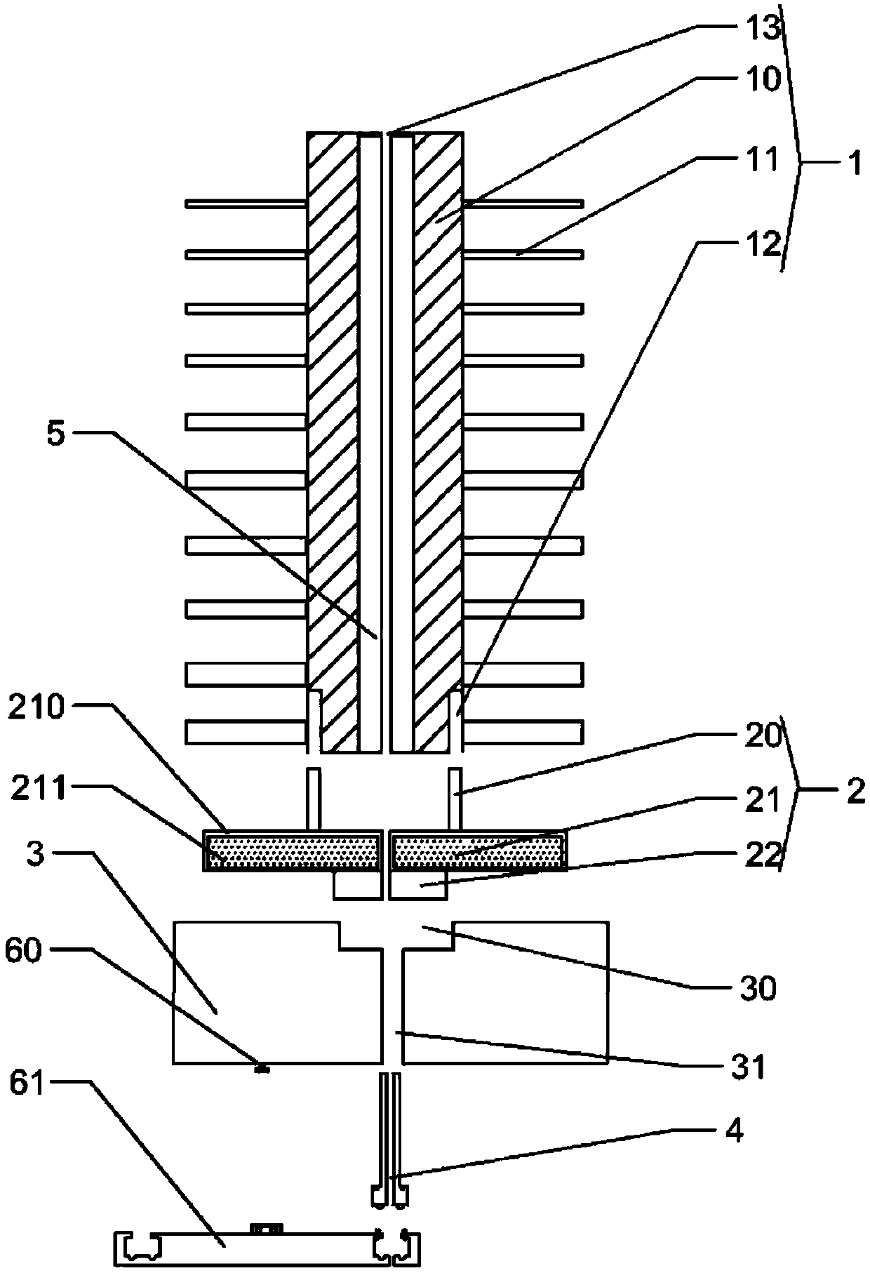
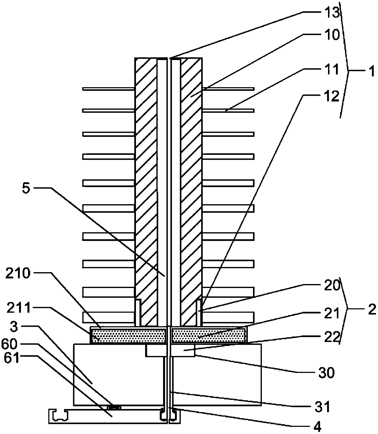
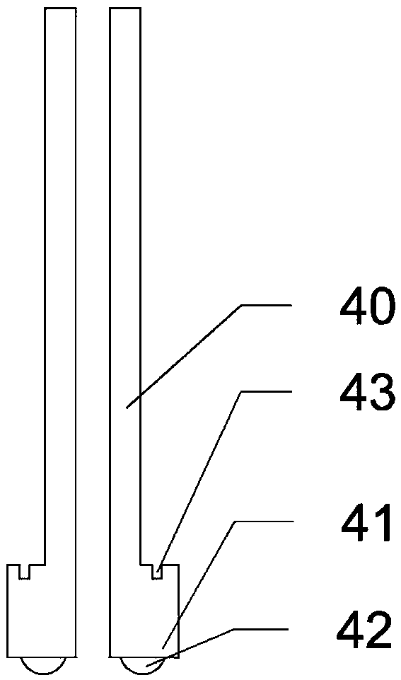
[0038] Such as Figure 1-6 As shown, the present invention provides an adjustable nozzle 4 assembly for a 3D printer, which includes a heat dissipation mechanism 1, a material guide tube 5, a heat insulation mechanism 2, a heating block 3 and a nozzle that are detachably connected and coaxially arranged from top to bottom. 4, characterized in that;

[0039] The heat insulation mechanism 2 includes an upper tube 20 , a middle tube 21 and a lower tube 22 which are integrally formed and communicated. Both the outer circumference of the upper tube 20 and the lower tube 22 have exter...


PUM

PropertyMeasurementUnit
thicknessaaaaaaaaaa

Abstract

The invention discloses an adjustable spray nozzle assembly for a 3D printer, the adjustable spray nozzle assembly comprises a thermal insulation mechanism, a heat dissipation mechanism, a material guiding pipe, a heating block, a spray nozzle, an adjusting mechanism and a circular disc, the thermal insulation mechanism comprises an upper pipe, a middle pipe and a lower pipe, the heat dissipation mechanism comprises a heat dissipation pipe, heat dissipation pieces and a groove, the upper pipe and the heat dissipation pipe are in screwed connection, one end of the material guiding pipe is attached to a shrink mouth, the other end of the material guiding pipe abuts on the upper surface of the middle pipe, the lower pipe and the heating block are in screwed connection, the spray nozzle comprises a screwing part and a sliding part, the screwing part and the heating block are in screwed connection, the adjusting mechanism includes an inverted T shaped rod; the circular disc includes an accommodating tank and a storage tank, the center of the bottom surface of the storage tank is provided with a plurality of extrusion holes, the upper end of the accommodating tank shrinks inward to form a shrinking part with a clamping opening, an upper thread hole cooperated with a lower thread hole of the screwing part is arranged on the shrinking part located above each extrusion hole, and when the spray nozzle and the circular disc are in screwed fixing, the center hole of the sliding part and one of the extrusion hole are in alignment. The adjustable spray nozzle assembly has the advantages of effective diffusion of heat transferred to the heat dissipation pipe, and by matched use of the spray nozzle and the adjusting mechanism, the pore size of the spray nozzle can be adjusted.

Description

technical field [0001] The invention relates to the technical field of 3D printing. More specifically, the present invention relates to an adjustable nozzle assembly for a 3D printer. Background technique [0002] Fused filament deposition modeling is currently the fastest-growing and most promising 3D printing rapid prototyping technology. The working principle of fused deposition modeling is that the hot-melt material, such as ABS, is first melted by the heater and drawn into a filament, and then the FDM molding equipment sends the filament-shaped printing material into the hot-melt nozzle through the wire feeding mechanism, and is drawn in the nozzle. Heating and melting, the nozzle moves along the section profile and filling trajectory of the part, extrudes the semi-fluid material according to the path controlled by the CAD layered data of the processed product, deposits it at the designated position, solidifies and forms, and bonds with the surrounding materials, layer...

Claims


Application Information

Patent Timeline
Patent Type & Authority Patents(China)
IPC IPC(8): B29C64/209B29C64/118B29C64/295B33Y30/00
CPCB33Y30/00
Inventor 施秀丽
Owner 山东爱舒乐卫生用品有限责任公司
Learn More