Torsion beam structure of rear suspension

A technology of torsion beam and rear suspension, applied in the direction of suspension, interconnection system, transportation and packaging, etc., can solve the problem that the length of the lap joint is not easy to control, the strength of the beam is low, and the installation structure of the front rubber bushing is unfavorable for the vehicle to understeer. characteristics and other issues, to achieve the effects of reducing the risk of X-direction misalignment and Y-direction lap length discomfort, high fatigue durability safety factor, and wide platform modification extensibility

Pending Publication Date: 2017-06-13
袁璐
View PDF18 Cites 8 Cited by
  • Summary
  • Abstract
  • Description
  • Claims
  • Application Information

AI Technical Summary

Problems solved by technology

[0003] (1) It is often difficult to press the front rubber bushing of the torsion beam structure of the rear suspension into the front sleeve of the torsion beam, and the installation structure of the front rubber bushing is not conducive to the understeering characteristics of the vehicle, so a large number of tests are required to verify the cost. high, long cycle
[0004] (2) The beam is directly stamped into a V or U shape by a plate. The beam has low strength and small roll angle stiffness. Usually, an additional torsion bar must be added to make up for the above performance defects.
However, in the test, the welding seam between the left and right ends of the torsion bar and the longitudinal arm often has tearing phenomenon, and the reliability is very poor.
[0005] (3) There are the following risks when the inner and outer plates of the trailing arm are fastened and welded. First, there is a risk of welding misalignment in the X direction of the inner and outer plates of the trailing arm. The length is not easy to control. If the overlapping side is short, the welding burn-through of the longitudinal arm will easily occur. If the overlapping side is long, the cross-sectional area of ​​the longitudinal arm will become smaller and the strength will be weakened.
This welding assembly method is not only labor-intensive, time-consuming, and costly, but also the support bracket and the flang

Method used


Image

  • Torsion beam structure of rear suspension
  • Torsion beam structure of rear suspension
  • Torsion beam structure of rear suspension

Examples


Embodiment Construction

[0049] The rear suspension torsion beam structure of the present invention will be further elaborated below in conjunction with specific embodiments, in order to make a more complete and clear description of the technical solution of the present invention.

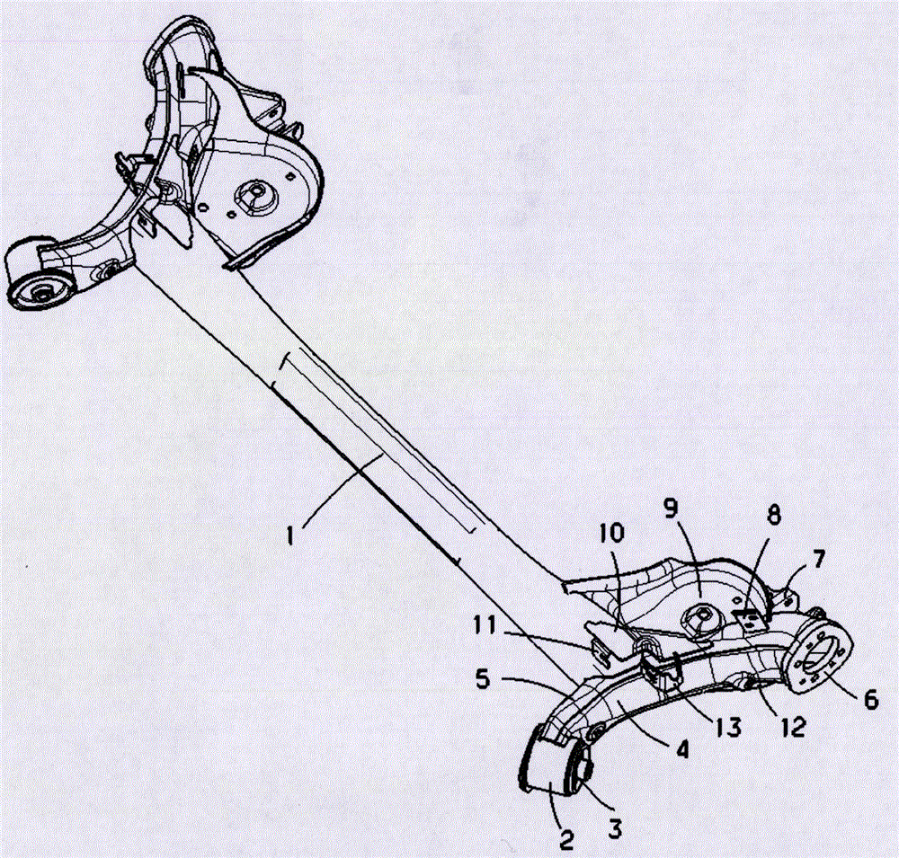
[0050] Such as figure 1 As shown, the rear suspension torsion beam of this embodiment includes a crossbeam 1, the two ends of the crossbeam are symmetrically provided with trailing arms, and the trailing arms are composed of a trailing arm outer plate 4 and a trailing arm inner plate 5. The welding ports at both ends of the beam 1 are respectively welded to the inner plate 5 of the longitudinal arm. The front bushing 2 is welded on the first ends of the trailing arm outer plate 4 and the trailing arm inner plate 5, and the front bushing assembly 3 is assembled in the front bushing 2. The trailing arm outer plate 4 and the trailing arm inner The second end of the plate 5 is welded with a brake base plate 6 . One side of t...


PUM


Abstract

The invention relates to a torsion beam structure of a rear suspension, and belongs to the technical field of suspensions of automobiles. The torsion beam structure of the rear suspension comprises a transverse beam, front sleeves, front lining assemblies, outer plates of longitudinal arms, inner plates of the longitudinal arms, a brake bottom plate, shock absorber supports, rear vertical harness supports, spring trays, triangular connecting plates, front vertical harness supports, spring tray reinforcement plates and hardness integrated supports, and the structures of the left side and the right side of a torsion beam are symmetric with each other. The torsion beam structure has the advantages that the torsion beam structure is designed under comprehensive consideration in multiple angles of performance, strength, reliability, stamping, welding, coating, assembling, materials and the like and is good in kinetic characteristic, high in fatigue and durability safety factor and wide in platform modification extensibility, components are high in structural strength, and manufacturing processes are feasible.

Description

technical field [0001] The invention relates to the technical field of automobile suspension systems, and more specifically, the invention relates to a rear suspension torsion beam structure. Background technique [0002] The torsion beam structure of the rear suspension is a kind of rear suspension of the car. It uses a torsion beam to balance the up and down jump of the left and right wheels, so as to reduce the shaking of the vehicle and keep the vehicle stable. The working principle of the rear suspension torsion beam structure is to install the non-independently suspended wheels at both ends of a torsion beam. When one wheel jumps up and down, the torsion beam will be twisted and deformed, thereby driving the other side of the wheel to jump accordingly. To reduce the tilt or shake of the entire vehicle body, because it has a certain torsional stiffness, it can play the same role as the stabilizer bar, which can increase the roll stiffness of the vehicle and improve the ...

Claims


Application Information

Patent Timeline
IPC IPC(8): B60G21/05
CPCB60G21/051B60G21/052
Inventor 袁璐
Owner 袁璐
Why Eureka
Try Eureka