Energy-saving pre-treatment type biological purification device for sewage

A sewage biological and purification device technology, applied in biological treatment devices, filtration treatment, water/sewage treatment, etc., can solve problems such as high energy consumption, impact on sewage treatment effects, sewage treatment accidents, etc., and achieve enhanced nitrogen and phosphorus removal effects , Enhance the effect of pretreatment and improve the purification effect

Inactive Publication Date: 2017-06-13
江苏鑫东方环保设备科技有限公司
View PDF0 Cites 0 Cited by
  • Summary
  • Abstract
  • Description
  • Claims
  • Application Information

AI Technical Summary

Problems solved by technology

[0002] At present, in the sewage biological treatment, the sequencing batch activated sludge process is widely used, such as the intermittent activated sludge process (SBR), the cycle activated sludge process (CASS) and other processes, there is no pre-reaction box at the front end, and the degassing The effect of nitrogen and phosphorus removal is not good, and the key equipment is the aerator and decanter. The performance of the aerator directly affects the effect of sewage treatment. The aerator is the equipment with the highest energy consumption in sewage treatment. Conventional treatment The aerator is always running during the process, so the power consumption is higher
The decanter affects the water outlet effect. A complete process cycle includes water intake, aeration, sedimentation, and drainage. During different cycles, the decanter needs to accurately complete different instructions, and the existing decanter often An error command occurs, causing the decanter to drop and discharge untreated sewage, causing sewage treatment accidents, and often also discharges scum on the water surface, resulting in poor drainage water quality

Method used


Image

  • Energy-saving pre-treatment type biological purification device for sewage

Examples


Embodiment Construction

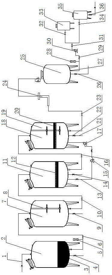
[0019] Such as figure 1 As shown, the energy-saving pretreatment sewage biological purification device includes a hydrolytic acidification biological tank 2, a pre-reaction tank 7, a continuous aeration water tank 11 and a sequence batch biological reaction water tank 18 connected in sequence.

[0020] The water inlet pipe 1 is connected to the upper part of the hydrolytic acidification biological box 2, the biological reaction filler 3 is arranged in the hydrolytic acidification biological box 2, and the first drain valve 4 is connected to the bottom of the hydrolytic acidification biological box 2.

[0021] Connect the first flow meter 5 and the first pneumatic angle seat valve 6 on the pipeline between the hydrolytic acidification biological box 2 and the pre-reaction box 7, connect the submersible mixer 8 in the pre-reaction box 7, and at the bottom of the pre-reaction box 7 Connect the second blowdown valve 9.

[0022] The second pneumatic angle seat valve 10 is connecte...


PUM


Abstract

The energy-saving pretreatment sewage biological purification device relates to the field of sewage treatment, including a hydrolytic acidification biological tank, a pre-reaction tank, a continuous aeration tank and a batch biological reaction tank connected in sequence; a submersible mixer is connected in the pre-reaction tank, and the continuous The overflow plate is connected in the aeration water tank, and the rectifying plate and the mixing agitator are connected in the sequence batch biological reaction water tank; the continuous aeration water tank is connected with the first aeration pipe and the blower, and the sequence batch biological reaction water tank and the continuous aeration water tank pass through the sludge The backflow pump is connected, and the sequence batch biological reaction tank is connected to the second aeration pipe; the sequence batch biological reaction tank is connected to the RO membrane filter through a buoy type decanter, and the pure water outlet of the RO membrane filter is connected to the booster pump, and the booster pump is connected to the A three-way joint, one water outlet of the three-way joint is connected to the pressure tank, the other water outlet is connected to the rear charcoal filter, and the rear charcoal filter is connected to the outlet faucet. The pretreatment effect is enhanced, the load of the subsequent process is reduced, the energy is saved and the purification effect is good.

Description

technical field [0001] The invention relates to the field of sewage treatment. Background technique [0002] At present, in the sewage biological treatment, the sequencing batch activated sludge process is widely used, such as the intermittent activated sludge process (SBR), the cycle activated sludge process (CASS) and other processes, there is no pre-reaction box at the front end, and the degassing The effect of nitrogen and phosphorus removal is not good, and the key equipment is the aerator and decanter. The performance of the aerator directly affects the effect of sewage treatment. The aerator is the equipment with the highest energy consumption in sewage treatment. Conventional treatment During the process, the aerator is always running, so the power consumption is high. The decanter affects the water outlet effect. A complete process cycle includes water intake, aeration, sedimentation, and drainage. During different cycles, the decanter needs to accurately complete ...

Claims


Application Information

Patent Timeline
Patent Type & Authority Applications(China)
IPC IPC(8): C02F9/14
CPCC02F9/00C02F1/001C02F1/283C02F1/441C02F3/2806C02F3/301C02F3/308C02F2203/004
Inventor 费广武屈撑囤杨文忠李金灵
Owner 江苏鑫东方环保设备科技有限公司
Why Eureka
Try Eureka