
Cutter die steel quenching production line, quenching method and cutter die steel machining method

A production line and knife die technology, applied in the direction of quenching agent, quenching device, manufacturing tools, etc., can solve problems such as the inability to meet the needs of normal production of knife belts, the inability to complete the exhaust work in a timely manner, and the erosion of the surrounding environment by harmful components. Heat treatment quality and production efficiency, improving heat treatment effect, and increasing the effect of isothermal heat treatment time

Active Publication Date: 2017-06-13
PUTIAN HENGDA MACHINERY & ELECTRICITY IND
View PDF8 Cites 3 Cited by
  • Summary
  • Abstract
  • Description
  • Claims
  • Application Information

AI Technical Summary

Problems solved by technology

[0003] The current process 4) heat treatment adopts lead bath furnace heat treatment. Since lead is used as the heat treatment medium, lead is an element harmful to the human body. Although it is collected and treated to purify the environment, there are still residual harmful components that erode our surroundings. The environment has brought harm to our life and work; after heat treatment, in order to cool the knife belt to the set temperature quickly, open cooling is adopted, and the smoke generated is collected by the exhaust system and processed, and the cost is low. High, wasteful, and because the cooling device is open, the amount of smoke is large, the temperature is high, the ventilation work cannot be completed in time, and it is difficult to collect and control the surrounding smoke in time, resulting in air pollution in the production workshop, which cannot meet the normal production requirements of the knife belt. need

Method used


Image

  • Cutter die steel quenching production line, quenching method and cutter die steel machining method
  • Cutter die steel quenching production line, quenching method and cutter die steel machining method
  • Cutter die steel quenching production line, quenching method and cutter die steel machining method

Examples


Embodiment Construction

[0046] In order to enable those skilled in the art to better understand the technical solutions of the present invention, the present invention will be further described in detail below in conjunction with the accompanying drawings and specific embodiments.

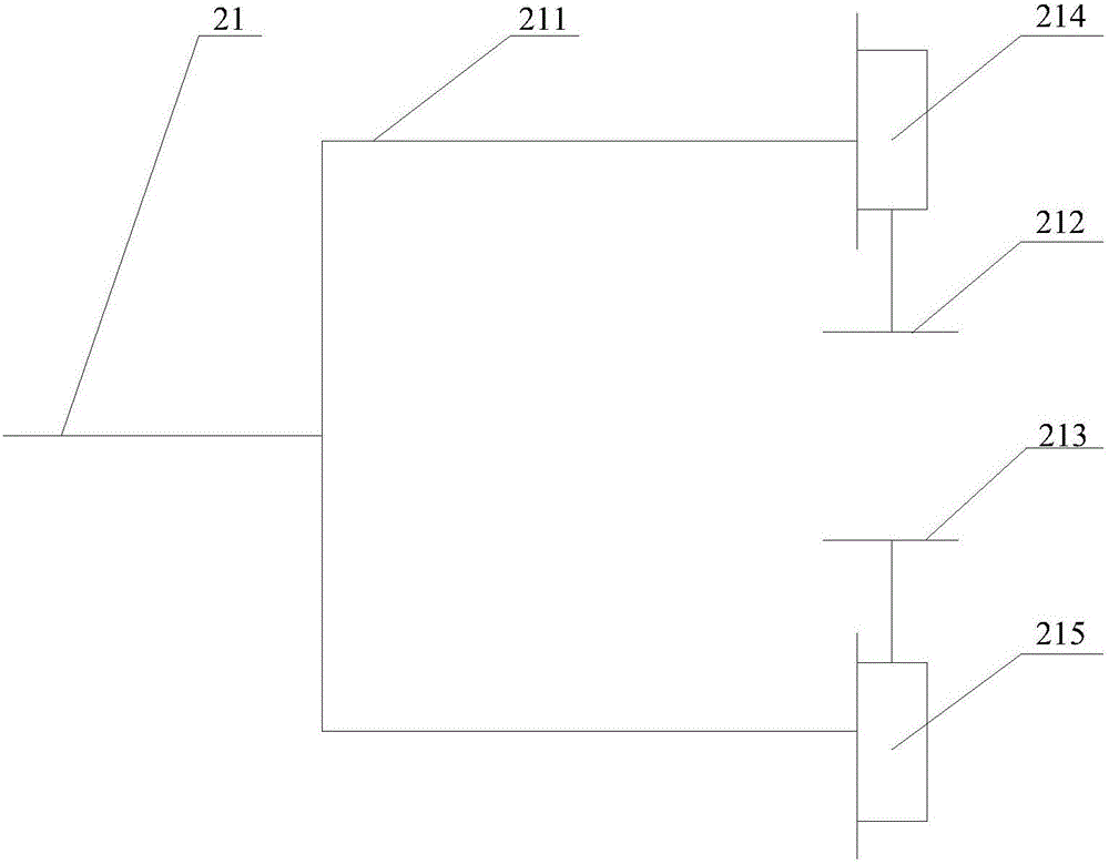
[0047] see figure 1 , is a structural schematic diagram of a cutting die steel quenching production line provided by the present invention. The invention discloses a die steel quenching production line, which comprises a feeding device 1, a pinch positioning device 2, a speed regulating device, an electric control device, a quenching furnace 3, a salt bath furnace 4, a tempering furnace 5, a cooling device 6 and a receiving device. Material device 7.

[0048] The feeding device 1 is used for providing die steel, wherein the feeding device 1 can place the die steel in coils.

[0049] The pinch positioning device 2 is used to transport the die steel conveyed by the feeding device to the preset station, wherein the preset st...


PUM

PropertyMeasurementUnit
thicknessaaaaaaaaaa

Abstract

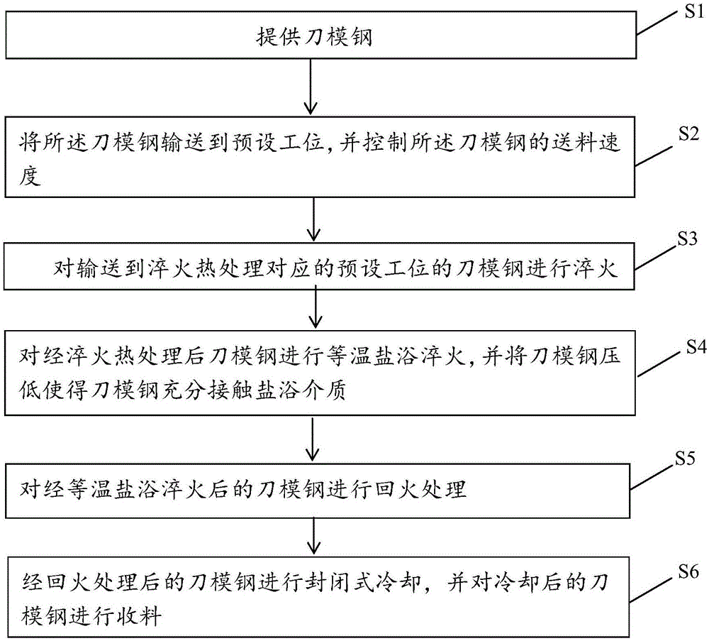
The invention discloses a cutter die steel quenching production line, a quenching method and a cutter die steel machining method. The cutter die steel quenching production line comprises a feeding device, a clamping, conveying and positioning device for conveying cutter die steel to a preset station, a speed adjusting device used for controlling the feeding speed of the cutter die steel, an electric control device electrically connected with the speed adjusting device and the clamping, conveying and positioning device, a quenching furnace arranged behind the feeding device, a salt-bath furnace which is arranged behind the quenching furnace and internally provided with a band guide roller for pressing the cutter die steel down, a tempering furnace arranged behind the salt-bath furnace, a closed cooling device which is arranged behind the tempering furnace and used for cooling the cutter die steel and a material collecting device which is arranged behind the cooling device and used for collecting materials. According to the cutter die steel quenching production line, an original lead-bath furnace is replaced by the isothermal salt-bath furnace, the production cost is reduced, and it is guaranteed that the surrounding environment is not corroded; and the cooling device is of a closed structure, collection of smoke in a sealed cavity is achieved, and it is guaranteed that the surrounding environment is not polluted and air purification is kept.

Description

technical field [0001] The invention relates to the technical field of die steel production equipment, in particular to a die steel quenching production line, a die steel quenching method and a die steel processing method. Background technique [0002] At present, the production of die steel is mainly processed by the following processes: 1) pickling: the raw material of die steel coil is passed through the pickling line to remove rust and dirt; 2) slitting: the pickled raw material is passed through Slitting machine into strips and coils; 3) Rolling: the die steel strip passed through the slitting machine is flattened and basically formed by rolling mill; 4) heat treatment: the rolled die steel strip is quenched and tempered in the heat treatment line Improve the hardness and toughness of the die steel; 5) Grinding: five grinding wheels are used to grade the die steel strip according to the requirements of the cutting edge; 6) Polishing: use a polishing machine to polish th...

Claims


Application Information

Patent Timeline
Patent Type & Authority Applications(China)
IPC IPC(8): C21D1/63C21D1/607C21D1/20B23P15/28
CPCB23P15/28C21D1/20C21D1/607C21D1/63
Inventor 林正华
Owner PUTIAN HENGDA MACHINERY & ELECTRICITY IND
Learn More