Continuous jig dyeing device for supercritical fluid and dyeing technology

A supercritical fluid, supercritical technology, applied in solvent dyeing, equipment configuration for processing textile materials, liquid/gas/vapor textile processing, etc., can solve the problems of short exposure time and low dyeing efficiency.

Active Publication Date: 2017-06-13
QINGDAO GUOBANG IND TECH DEV CO LTD +1
View PDF13 Cites 6 Cited by
  • Summary
  • Abstract
  • Description
  • Claims
  • Application Information

AI Technical Summary

Problems solved by technology

Because the dyed object in this patent only goes back and forth once between the two cloth rolling rolle

Method used


Image

  • Continuous jig dyeing device for supercritical fluid and dyeing technology
  • Continuous jig dyeing device for supercritical fluid and dyeing technology
  • Continuous jig dyeing device for supercritical fluid and dyeing technology

Examples


Embodiment 1

[0074] Example 1: Double integrated dyeing jigger supercritical fluid continuous dyeing device and dyeing process

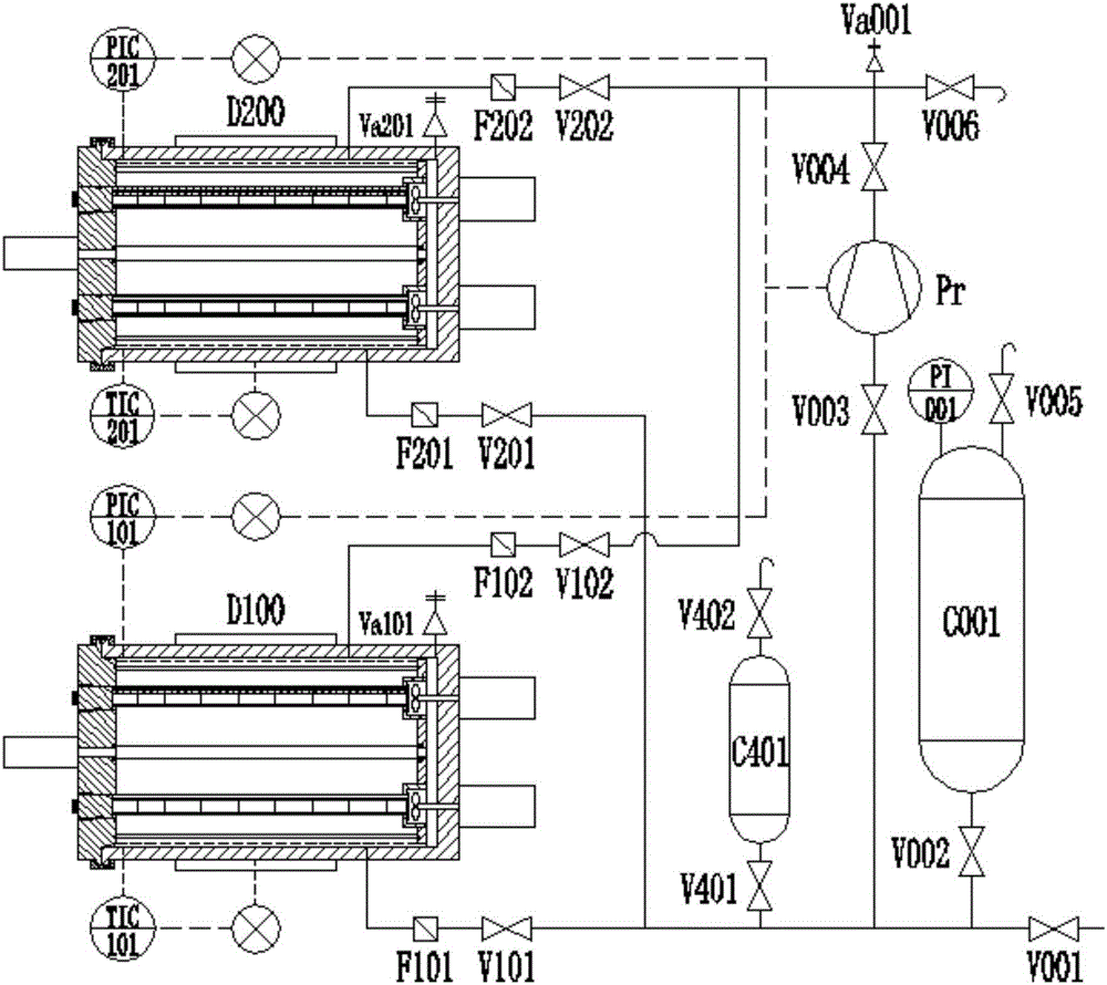
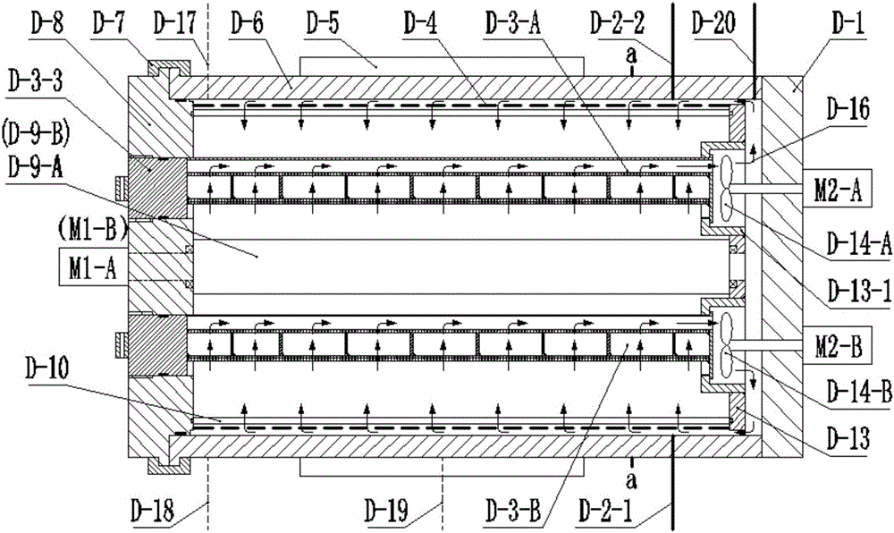
[0075] Such as figure 1 As shown, the double integrated jigger supercritical fluid continuous dyeing device of the present invention consists of two integrated jiggers with the same structure, namely integrated jigger A D100 and integrated jigger B D200, filters F101, F102, F201, F202, booster Pr, supply tank C001, buffer tank C401, supply valve V001, switching valves V002, V003, V004, V101, V102, V201, V202, V401, emptying valves V005, V402, emptying valve V006, Safety valves Va001, Va101, Va201, temperature control instruments TIC101, TIC201, pressure control instruments PIC101, PIC201, pressure display instrument PI001, and pipes and fittings. Such as image 3 As shown, the integrated dye jiggers are equipped with pressure control instrument connection D-17, temperature control instrument connection D-18, heater temperature control wiring D-19, safety valve ...

Embodiment 2

[0093] Example 2: Three-integrated dyeing jigger supercritical fluid continuous dyeing device and dyeing process

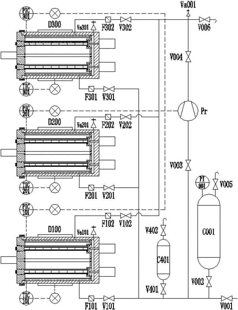
[0094] Such as figure 2 As shown, the supercritical fluid continuous dyeing device of the present invention consists of three integrated jiggers with the same structure, i.e. integrated jigger A D100, integrated jigger B D200 and integrated jigger CD300, filter F101, F102, F201, F202, F301, F302, supercharger Pr, supply tank C001, buffer tank C401, switching valve V002, V003, V004, V101, V102, V201, V202, V301, V302, V401, emptying valve V005, V402, vent valve V006, safety valves Va001, Va101, Va201, Va301, temperature control instruments TIC101, TIC201, TIC301, pressure control instruments PIC101, PIC201, PIC301, pressure display instrument PI001, and pipes and fittings. Such as image 3 As shown, the integrated dye jiggers are equipped with pressure control instrument connection D-17, temperature control instrument connection D-18, heater temperature control ...


PUM


Abstract

The invention relates to the field of textile dyeing, in particular to a continuous jig dyeing device for supercritical fluid and a dyeing technology. The double-integrated jig dyeing device or three-integrated jig dyeing device continuous jig dyeing device for supercritical fluid is composed of two or three integrated jig dyeing devices, filters, a booster, a supply tank, a buffering tank, switching valves, a supply valve, blow-off valves, an emptying valve, safety valves, a pressure display gauge, pressure control gauges, temperature control gauges, pipes and pipe fittings. The technology includes the steps that 1, system is initialized; the integrated jig dyeing devices are initialized; 3, feeding of supercritical fluid media, supercriticality and jig dyeing are carried out on the integrated jig dyeing devices; 4, feeding of supercritical fluid media, supercriticality and rinsing are carried out on the integrated jig dyeing devices again; 5, pollutants are discharged from the integrated jig dyeing devices. According to the device and the dyeing technology thereof, the process is simple and convenient to implement, preparation time before dyeing is short, equipment investment is small, production efficiency is high, operation cost is low, and emissions of the supercritical fluid media are low.

Description

[0001] 1. Technical field [0002] The invention relates to the field of textile dyeing, in particular to a supercritical fluid continuous dyeing device and a dyeing process. [0003] 2. Technical background [0004] The traditional water dyeing process will bring a large amount of industrial wastewater, and the water pollution problem seriously restricts the development of the traditional dyeing industry. At present, the proportion of water reuse in the traditional water dyeing production process is very low, and the cost of sewage treatment is high. [0005] Supercritical fluid dyeing uses supercritical fluid, especially supercritical carbon dioxide, to replace water as the carrier of dyes for dyeing, realizing anhydrous dyeing, thereby fundamentally solving the problem of water pollution in the dyeing industry, and has a good development and application prospect. [0006] Summarizing the characteristics of the existing supercritical fluid dyeing process, it can be seen that...

Claims


Application Information

Patent Timeline
IPC IPC(8): D06B3/32D06B9/02D06B23/20
CPCD06B3/32D06B9/02D06B23/20D06B19/00
Inventor 王威强王胜德曲延鹏郭洪晓崔书瑞于丽杰
Owner QINGDAO GUOBANG IND TECH DEV CO LTD
Why Eureka
Try Eureka