
A vacuum aluminum plating machine

A technology of vacuum aluminum plating and aluminum film coating, which is applied in the field of machinery, can solve the problems of expensive equipment, aluminum film is easy to wrinkle, and affects product quality, etc., and achieves the effects of uniform feeding speed, preventing wrinkling, and good neutrality

Active Publication Date: 2019-02-01
浙江长宇新材料股份有限公司
View PDF5 Cites 0 Cited by
  • Summary
  • Abstract
  • Description
  • Claims
  • Application Information

AI Technical Summary

Problems solved by technology

[0003] The vacuum aluminum coating machine has an aluminum coating room and a winding room. Because the existence of water vapor in the winding room and the aluminum coating room affects the vacuum degree in the room, it is necessary to use an air extraction device to extract the water vapor or directly condense the water vapor into a vacuum. into solid water, if the pumping equipment is used to pump water vapor, it will increase the pre-vacuum time before coating and reduce the efficiency of the vacuum aluminum coating machine. In practical industrial applications, the vacuum aluminum coating machine is due to the winding chamber and The aluminum plating room is connected, so the overall equipment is very expensive. If the efficiency of the vacuum aluminum plating machine decreases, its economic benefits will inevitably decrease
[0004] In the process of aluminum plating by vacuum aluminum plating method, the lack of necessary drying device will affect the aluminum plating effect of the product during the transmission process of the aluminum film in the aluminum plating equipment, and the aluminum film is easy to wrinkle and affect the product quality

Method used


Image

  • A vacuum aluminum plating machine
  • A vacuum aluminum plating machine
  • A vacuum aluminum plating machine

Examples


Embodiment Construction

[0023] The following are specific embodiments of the present invention and in conjunction with the accompanying drawings, the technical solutions of the present invention are further described, but the present invention is not limited to these embodiments.

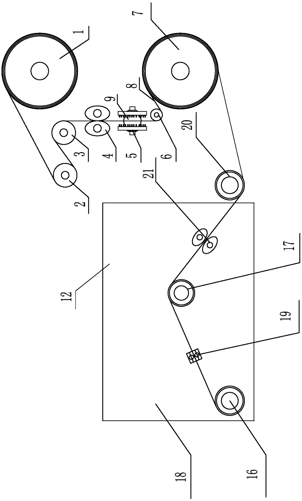
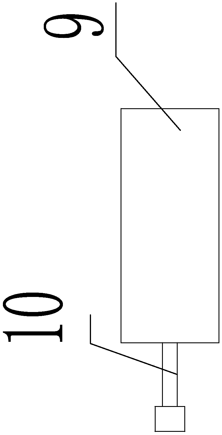
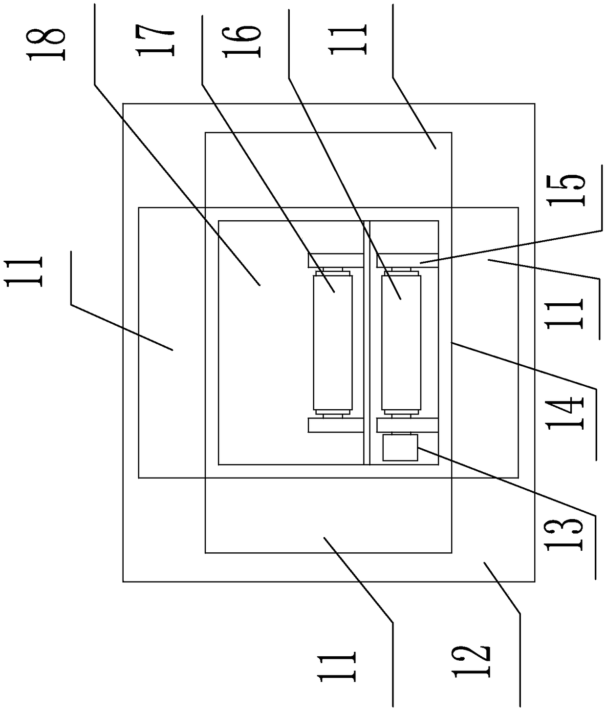
[0024] Such as figure 1 , figure 2 As shown, the vacuum aluminum plating machine includes a centralizing mechanism and a drying mechanism, and the centralizing mechanism includes a first roller 1, a first guide roller 2, a second guide roller 3, a centralizing roller 4, a high-temperature air injection device 5, a tension pulley 6, The second roller 7, the aluminized film 8, the high temperature evaporator 9 and the gas delivery pipe 10; the aluminized film 8 wound on the first roller 1 passes through the first guide roller 2 and the second guide roller 3 in turn, and is located on the second guide roller The aluminized film 8 on the 3 passes through the gap between the two centering rollers 4 and the high-temperature ai...


PUM


Abstract

The invention provides a vacuum aluminum plating machine. The vacuum aluminum plating machine comprises a centralizing mechanism and a drying mechanism which are arranged on a conveying line of an aluminum-plated film; the centralizing mechanism comprises a first roller, a first guide roller, a second guide roller, centralizing rollers, high-temperature gas injection devices, a tensioning wheel I, a second roller, the aluminum-plated film, a high-temperature evaporator and gas conveying pipes; the high-temperature evaporator is connected with the high-temperature gas injection devices through the gas conveying pipes on the two sides; the drying mechanism comprises a high-temperature gas feeding cavity, a drying device casing, a belt wheel, a heat transfer wall, support seats, a discharging roller, a third guide roller, a hollow cavity, a tensioning wheel II, a tightening roller and guiding rollers; and the aluminum-plated film located on the discharging roller sequentially passes through the tensioning wheel II, the third guide roller and the guiding rollers to wind around the tightening roller. By the aid of high-temperature gas fed into the high-temperature gas feeding cavity, the condition that the product quality is affected due to the fact that the aluminum-plated film makes direct contact with a heat source is avoided, and the high-temperature gas can be recycled, so that resources are saved, and the drying effect is good.

Description

technical field [0001] The invention belongs to the technical field of machinery and relates to a vacuum aluminum plating machine. Background technique [0002] Aluminized film is a kind of composite flexible packaging material formed by coating a layer of extremely thin metal aluminum on the surface of plastic film by a special process. The most commonly used processing method is the vacuum aluminized method. Because it has both the characteristics of plastic film and the characteristics of metal, it is a cheap and beautiful packaging material with excellent performance and strong practicability. [0003] The vacuum aluminum coating machine has an aluminum coating room and a winding room. Because the existence of water vapor in the winding room and the aluminum coating room affects the vacuum degree in the room, it is necessary to use an air extraction device to extract the water vapor or directly condense the water vapor into a vacuum. into solid water, if the pumping equ...

Claims


Application Information

Patent Timeline
Patent Type & Authority Patents(China)
IPC IPC(8): F26B13/14F26B21/00C23C14/20C23C14/24C23C14/56
CPCC23C14/20C23C14/24C23C14/562F26B13/14F26B21/004
Inventor 吴明忠吴林海张孝中曾祥平熊燕斌吴建松陆志刚朱佳郑海艳
Owner 浙江长宇新材料股份有限公司
Learn More