
Belt-type dry cooler

A belt-type drying, drying and cooling technology, applied in the direction of dryers, drying solid materials, dry cargo handling, etc., can solve the problems of unsatisfactory effect, no distributor, easy to break, etc., to save heat loss and fully cool Uniform and reduce breakage effect

Active Publication Date: 2017-06-13
JIANGSU MUYANG HLDG
View PDF7 Cites 8 Cited by
  • Summary
  • Abstract
  • Description
  • Claims
  • Application Information

AI Technical Summary

Problems solved by technology

However, this type of dryer has no distributor (responsible for feeding and uniform distribution of materials), no powder removal device, and no feet (responsible for the support of the whole machine and reserved space for the powder removal device) in the structure, and its drying principle is similar. : The material layer is driven forward by the belt tube, and the hot air passes through the material from bottom to top to achieve the purpose of drying; after that, the material is cooled to meet the requirements of packaging and storage
[0003] At present, the main dry coolers in the market have the problems of high energy consumption and poor moisture uniformity, specifically:
[0004] 1. High energy consumption, because all the hot air passing through the material layer is directly discharged by the centrifugal exhaust fan, and does not participate in the next drying cycle; and the material is loaded with a fixed pallet type, and its opening The rate is small, resulting in the need for a large air volume to ensure the drying of the material, further increasing the energy consumption
[0005] 2. Poor moisture uniformity, which is mainly caused by the way it is distributed, because the material falls on the distribution board only by gravity, and the angle of the distribution board is adjustable. The effect of material layer thickness
However, the actual production effect is very unsatisfactory. At the same time, the material is easily broken due to the impact force.

Method used


Image

  • Belt-type dry cooler
  • Belt-type dry cooler
  • Belt-type dry cooler

Examples


Embodiment Construction

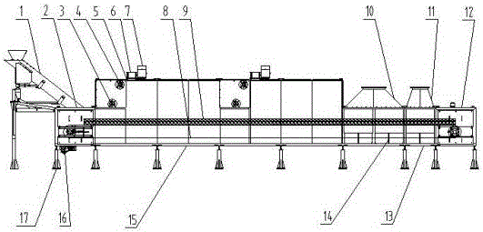
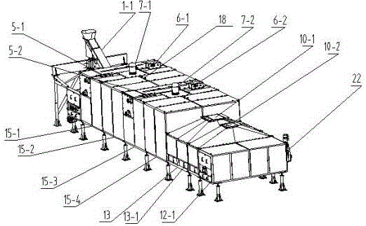
[0032] A belt-type drying and cooling machine, the drying and cooling machine includes a distributor 1, a feed section 2, a drying section 15, a cooling section 13, a discharge section 12 and a foot 17, and the distributor 1 is connected with a cloth The device chute 1-1 is connected to the feed section 2, and the conveyor belt 8 inside the drying cooler passes through the drying section 15, the drying section 15, the cooling section 13 and the discharge section 12 successively, and the described drying section 15 includes at least one In the drying zone, the upper part of each drying zone is independently provided with a make-up air outlet, an air exhaust outlet, a circulation fan, a hot air inlet, a temperature sensor 18 and a heat exchanger 19, and the cooling section 13 includes one or two cooling zones, each cooling There are independent air ducts, exhaust fans and air inlets in each zone, and two windshields 15-5 are arranged between adjacent drying zones, and three winds...


PUM


Abstract

The invention relates to a belt-type dry cooler which comprises a distributing device, a feeding section, a drying section, a cooling section and a discharging section. The distributing device is communicated with the feeding section through a distributing-device hosepipe connected on the distributing device, and a conveying belt in the dry cooler sequentially penetrates the feeding section, the drying section, the cooling section and the discharging section; the drying section comprises at least one drying area, and an air supplement port, an air outlet, a circulating fan, a hot-air inlet, a temperature sensor and a heat exchanger are independently arranged on the upper portion of each drying area; the cooling section comprises at least one cooling area, each cooling area is provided with an independent air duct, an exhaust fan and an air inlet, a second wind screen is arranged between every two neighboring drying areas, and a third wind screen is arranged between the drying section and the cooling section. The distributing device is under variable frequency control, hot air is capable of operating in a more balanced and stable manner through reasonable air-inlet and-outlet arrangement and a tight sealing structure, and dried materials are ensured to be uniform in moisture.

Description

technical field [0001] The invention relates to an integrated drying and cooling machine for materials (including corn, barley, sorghum and other grain tablet materials, as well as foods such as breakfast chips, potato chips and tissue protein), especially a belt-type drying and cooling machine. Background technique [0002] At present, the fixed pallet type hot air dryer is commonly used in the grain, feed and food industries. This type of dryer has a feeding section (responsible for inputting materials), a material distribution device (angle-adjustable material distribution board), and a ventilation pallet (responsible for carrying materials). , with material pipe (responsible for conveying materials), drying section (responsible for removing moisture and gelatinized materials), cooling section (responsible for cooling materials), discharge section (responsible for outputting materials), heating system (responsible for providing material drying heat). However, this type o...

Claims


Application Information

Patent Timeline
Patent Type & Authority Applications(China)
IPC IPC(8): F26B17/04F26B21/00F26B25/00
CPCF26B17/04F26B21/002F26B21/004F26B25/00F26B25/002
Inventor 裴照辉张鹏飞张季伟李元祥
Owner JIANGSU MUYANG HLDG
Learn More