
Loading device suitable for static test of composite wings

A composite material and static test technology, applied in the field of aviation static test, can solve the problems of bulky loading device, difficult installation, large local load, etc., and achieve flexible and changeable application point positions, saving test funds, and good versatility Effect

Inactive Publication Date: 2017-06-13
R&D INST OF CHINA AVIATION IND GENERAL AIRCRAFT
View PDF6 Cites 4 Cited by
  • Summary
  • Abstract
  • Description
  • Claims
  • Application Information

AI Technical Summary

Problems solved by technology

This method is no problem for metal wings, and has been verified by many models, but for composite wings, especially when the loading point is very close to the edge of the wing surface, there are fewer distributed application points. Causes excessive local loads, leading to problems such as delamination of the wing skin
[0006] In addition to the tape (tension and pressure pad) loading, there is also a loading method for the whole airfoil pallet loading. The loading of this loading device is relatively uniform, and it also adopts the principle of changing the tension load into ballast load, but this loading device is generally are bulky, making installation difficult
The full-wing clamping plate and the airfoil bonding device are generally thick and disposable items. When testing other wings, it is necessary to re-produce another bonding device, resulting in a waste of resources

Method used


Image

  • Loading device suitable for static test of composite wings
  • Loading device suitable for static test of composite wings

Examples


Embodiment Construction

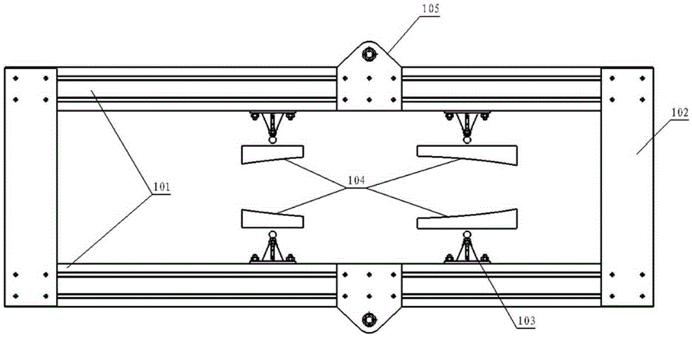
[0016] There are T-shaped grooves on four sides of the main load-bearing beam 101, and the test load application plate 105 can slide freely in 101, so that the load application position is more flexible. When the connection strength between 105 and 101 is insufficient, multiple 105 and 101 can be connected. For connection, each 105 is applied in the form of a lever to reduce the local connection strength. When there is interference with the loading point near the loading device, it can be connected through multiple 105 and 101 far away from the interference area, and each 105 is applied in the form of a lever to reduce the possibility of load application interference.

[0017] The upper and lower beam connecting plates 102 can slide arbitrarily in 101, so that the present invention can be applied to airfoils of different sizes. When the airfoil is just suitable for the longest length of 101, 102 is placed on the most end surface. When the airfoil is less than 101, the longest ...


PUM


Abstract

The invention provides a loading device suitable for static test of composite wings. The loading device suitable for static test of composite wings comprises a main bearing crossbeam, upper and lower beam connecting plates, loading centers, wing loading pads and test loading applying plates. The loading device suitable for static test of composite wings is characterized in that an integral frame is formed by the main bearing crossbeam, the upper and the lower beam connecting plates, and the loading centers; the concentrated load from the test load applied to the plate is changed into several small concentrated loads and a load block is loaded from the wing contacting the load thimble, and a plurality of small concentrated loads are distributed into a uniformly distributed load to the wing skin. The loading device suitable for static test of composite wings adopted is capable of changing the normal tensile load applied to the wing into a localized load on the skin, and the delamination problem caused by too large local tension of composite materials is avoided, meanwhile, because of the flexibility of each component connection, the loading device suitable for static test of composite wings can be loading applying in the static test load for a plurality of airfoils and a plurality of loading points.

Description

[0001] Technical field: [0002] The invention belongs to the field of aviation static test and relates to a loading device suitable for composite material wing static test. [0003] Background technique: [0004] As an important bearing part of an aircraft, the strength of the wing directly affects the flight safety of the aircraft. Therefore, the strength of the wing needs to be verified by static tests. The maximum carrying capacity of the wing has always been one of the most concerned issues of the structural strength of the aircraft, and it is also the key to determining the performance and carrying capacity of the aircraft. Accurate test load application device and application method can make the data obtained in the test closer to reality, can better promote the development of theoretical analysis, and make the structural strength design of the wing approach to perfection. [0005] In the past, the loading of the wing was mainly carried out with adhesive tape, and late...

Claims


Application Information

Patent Timeline
Patent Type & Authority Applications(China)
IPC IPC(8): G01M13/00
Inventor 贾炜琰邱晨王鹏飞
Owner R&D INST OF CHINA AVIATION IND GENERAL AIRCRAFT
Learn More