
Tension-torsion combined fretting fatigue testing device and testing method thereof

A test equipment, fretting fatigue technology, used in the application of repetitive force/pulsation force to test the strength of materials, measuring devices, instruments, etc., which can solve the problems of poor test results, complex equipment, parameter bending, etc.

Active Publication Date: 2017-06-13
SOUTHWEST JIAOTONG UNIV
View PDF9 Cites 8 Cited by
  • Summary
  • Abstract
  • Description
  • Claims
  • Application Information

AI Technical Summary

Problems solved by technology

[0005] At present, the research on fretting fatigue mainly focuses on the tension-compression mode, and the international fretting fatigue research on wheel shaft materials is also limited to the tension-compression mode. In the fretting fatigue test, the horizontal (normal direction) ) load, so that the fretting pads on both sides maintain a press fit (tight fit) with the sample. At present, the equipment for testing in this way is complicated, and the test results are poor. The sample is prone to parametric bending during the loading process. Moreover, it is difficult to measure the strain displacement change during the test.

Method used


Image

  • Tension-torsion combined fretting fatigue testing device and testing method thereof
  • Tension-torsion combined fretting fatigue testing device and testing method thereof
  • Tension-torsion combined fretting fatigue testing device and testing method thereof

Examples


Embodiment Construction

[0027] Specific embodiments of the present invention are described below so that those skilled in the art can understand the present invention, but it should be clear that the present invention is not limited to the scope of specific embodiments. For those of ordinary skill in the art, as long as various changes Within the spirit and scope of the present invention defined and determined by the appended claims, these changes are obvious, and all inventions and creations using the concept of the present invention are included in the protection list.

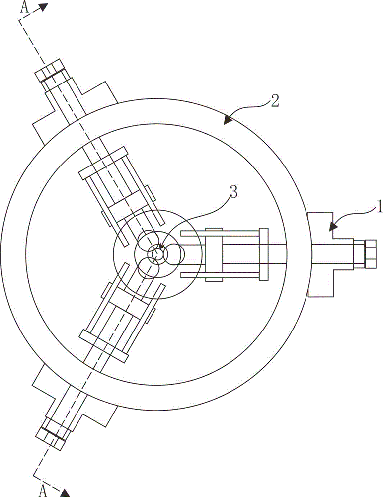
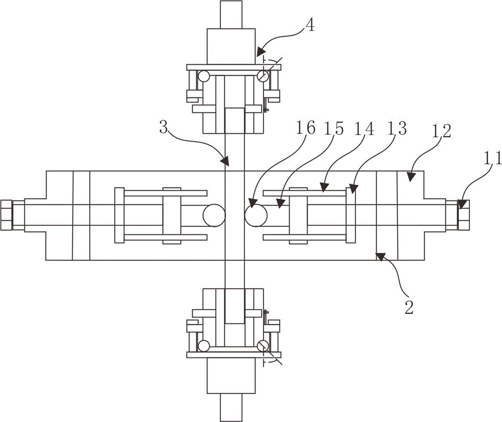
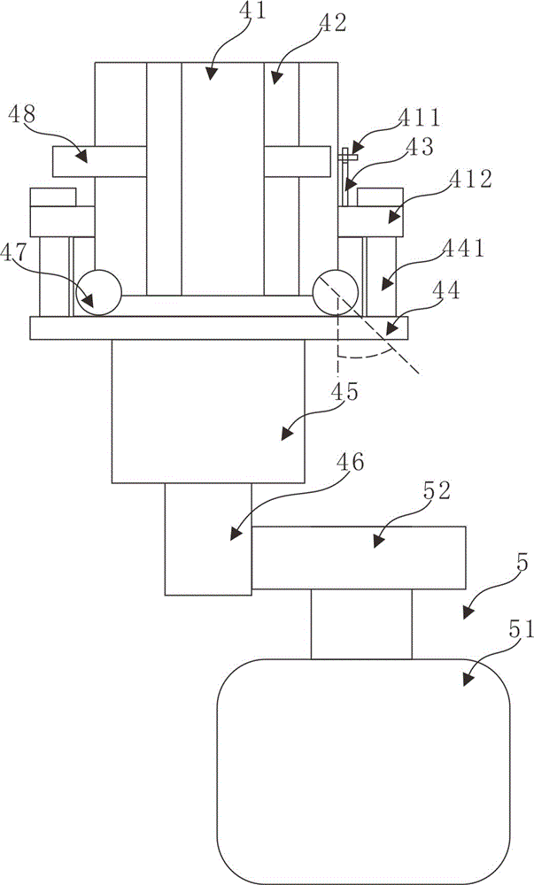
[0028] refer to figure 1 and image 3 , figure 1 It shows the top view of the installation ring 2, the radial positioning device 1 and the loading device 4 assembled together to clamp the sample shaft 3 of the tension-torsion compound fretting fatigue test equipment, image 3 A schematic structural diagram of the assembly of the loading device 4 and the power device 6 of the tension-torsion compound fretting fatigue test equipmen...


PUM


Abstract

The invention discloses a tension-torsion combined fretting fatigue testing device and a testing method thereof. The tension-torsion combined fretting fatigue testing device comprises a mounting ring, radial positioning devices, loading devices, power devices and image collection devices, wherein the image collection devices are used for collecting radial images of a sample shaft; a three-dimensional sensor is arranged in a contact position between each radial positioning device and a sample shaft; each loading device comprises a sleeve; a ring-shaped boss is arranged in the middle of each sleeve; at least three arc-shaped grooves are formed in the edge of the bottom of each sleeve; clamping plates are arranged in each sleeve at equal intervals; each clamping plate is mounted in a threaded hole of each sleeve through a stud fixedly arranged on the clamping plate; after balls are placed in the arc-shaped grooves of each sleeve, the lower end of the sleeve is placed in a receiving tank; a fixing shaft is fixedly connected with a worm rod through a coupler; each power device comprises an electromotor; a worm wheel arranged on an output shaft of each electromotor is meshed with the worm rod; an angle collector used for collecting rotation angles of the sample shaft during test is arranged on each ring-shaped boss.

Description

technical field [0001] The invention belongs to the field of interference fit fatigue testing of wheel shafts, and in particular relates to a tension-torsion compound fretting fatigue test equipment and a test method. Background technique [0002] Fretting fatigue refers to the relative displacement of extremely small amplitude (micron level) between the contact surfaces of two contacting workpieces due to alternating loads such as mechanical vibration, fatigue load, electromagnetic vibration or thermal cycle. High stress concentration and wear fatigue behavior. [0003] Fretting fatigue widely exists in fastening and fitting components in various industrial fields such as machinery industry, railway, nuclear power, aerospace, bridges, ships, etc. Its hazards are very serious and terrible, and it has become the main reason for the failure of many key components. Reasons, such as: rivet connection, threaded connection, pin shaft connection and other connecting parts, spline ...

Claims


Application Information

Patent Timeline
Patent Type & Authority Applications(China)
IPC IPC(8): G01N3/38
CPCG01N3/38G01N2203/0005
Inventor 朱旻昊彭金方任岩平贺继樊蔡振兵章武林刘曦洋金潇刘学通
Owner SOUTHWEST JIAOTONG UNIV
Learn More