
An experimental method and experimental device for debris flow simulation and dynamic parameter acquisition

A technology of dynamic parameters and experimental equipment, applied in the field of geological research, can solve the problems of inability to monitor the experimental data, explain the diversity of debris flow, and the difficulty of monitoring the movement state, etc., and achieve the effect of precise migration process

Inactive Publication Date: 2019-03-12
CHENGDU UNIVERSITY OF TECHNOLOGY
View PDF5 Cites 0 Cited by
  • Summary
  • Abstract
  • Description
  • Claims
  • Application Information

AI Technical Summary

Problems solved by technology

[0004] (1) Limited by the length of the chute, it is impossible to simulate the high-speed motion state of debris flow migration
[0005] (2) Only a single release of the debris flow can be achieved each time, and the height of the debris flow is roughly fixed. It is impossible to simulate the different movement speeds of the debris flow, and the diversity of the debris flow cannot be explained clearly
[0006] (3) The time of each test is short, and the process from the start, migration, and stagnation of the debris flow is usually completed within 1 to 2 seconds, and there is not enough time to observe and record the movement state of the debris flow during the test Interaction with detritus particles
[0007] (4) It is difficult to monitor the motion state. Due to the short test process, effective test data cannot be monitored, such as the velocity of the debris flow, the force between the debris flow and the substrate, and the interaction of particles inside the debris flow, etc.

Method used


Image

  • An experimental method and experimental device for debris flow simulation and dynamic parameter acquisition
  • An experimental method and experimental device for debris flow simulation and dynamic parameter acquisition
  • An experimental method and experimental device for debris flow simulation and dynamic parameter acquisition

Examples


Embodiment

[0032] see Figure 4-6 , a debris flow simulation experiment device, including a rotating drum 8, a driving device 9 for driving the rotating drum 8, and a bracket 7 for carrying the rotating drum 8 and the driving device 9, this implementation The rear side panel 11 of example rotating drum body 8 is a steel plate material, and rear side panel 11 is provided with feeding port 12, and the front side panel of rotating drum body 8 is transparent glass fiber reinforced plastics, to serve as debris flow when rotating drum body 8 rotates. Observation window, the driving device 9 of the present embodiment is a driving wheel, the driving wheel is four, and symmetrically arranged at both ends of the bottom of the support 7, and tangent to the rotating drum 8, the driving wheel adopts Driven by synchronous motor,

[0033] It is also provided with a speed adjustment device for adjusting the speed of the driving wheel, and a liquid crystal panel for displaying the linear speed of the ro...


PUM


Abstract

The invention discloses an experiment device for simulating debris flow and acquiring dynamic parameters. The device comprises a rotary drum, a drive device and a support, wherein the drive device is used for driving the rotary drum, the support is used for supporting the rotary drum and the drive device, the rear panel of the rotary drum is provided with a feed inlet, the front panel of the rotary drum is made of transparent materials, and the drive device is a drive wheel driven by a motor. The invention further discloses an experiment method using the device. The device has the advantages that debris materials in the rotary drum rotate in a circulating manner, the length of a slide groove is increased equivalently, the flowing process of the debris flow is allowed to be in an unlimited duration state or a controllable duration state, the movement process of the debris flow is simulated precisely, the flowing state of the debris flow can be visually observed, and a large instrument setting space can be obtained to acquire the debris flow dynamic parameters.

Description

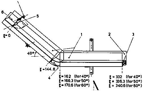
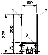
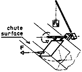
technical field [0001] The invention relates to the technical field of geological research, in particular to an experimental method and experimental device for debris flow simulation and dynamic parameter acquisition. Background technique [0002] A debris flow is a high density fluid mixture of sand, gravel, clay material and water that flows down a slope under the force of gravity. In order to conduct relevant research on debris flow movement, simulation devices are generally used in this field for simulation. The device used in the existing simulation method, the general structure is as follows Figure 1-3 As shown, the chute is made of plexiglass and PVC plastic. The chute includes the front side plate 1 of the chute, the rear side plate of the chute, the bottom panel 3 of the chute and the corner chute assembly 4. figure 1 The debris flow material placement space 6 on the top of the chute is shown, and the bolt F is pulled out to open the gate 5 to simulate the start,...

Claims


Application Information

Patent Timeline
IPC IPC(8): G01N33/24
CPCG01N33/24
Inventor 许强姜照勇郑光朱星周小棚董远峰
Owner CHENGDU UNIVERSITY OF TECHNOLOGY
Learn More