Direct type millimeter wave signal detection instrument of silicon slot coupled T junctions

A signal detection and millimeter wave technology, which is applied in the field of direct millimeter wave signal detection instruments, can solve the problems that the range of millimeter wave detection technology is not very large, is particularly perfect from time to time, and has a complex structure, and achieves high potential application value and simple structure Novel, efficiency-enhancing effects

Active Publication Date: 2017-06-13
SOUTHEAST UNIV
View PDF14 Cites 0 Cited by
  • Summary
  • Abstract
  • Description
  • Claims
  • Application Information

AI Technical Summary

Problems solved by technology

[0002] The 21st century is the era of information science and technology. In this era of rapid development, signal detection, as an important science and technology, has been deeply studied, especially in today's military, communication, aerospace and other fields. The detection of various signals is a very important task. A signal has three very important parameters: frequency, phase and power. According to frequency, it can be divided into low frequency signal, high frequency signal and extremely high frequency signal. , where the millimeter-wave signal is an extremely high-frequency signal, which is located in the area where microwaves and far-infrared waves overlap. At present, the detection technology for extremely high-frequency millimeter-wave signals is still perfect from time to time. Most of today's signal detectors only The frequency, phase and power of the signal can be measured separately. The integration level is not very high, and their structures are relatively complex, with many high-frequency effects. Due to these constraints, the range of millimeter wave detection technology is not very large. Big

Method used


Image

  • Direct type millimeter wave signal detection instrument of silicon slot coupled T junctions
  • Direct type millimeter wave signal detection instrument of silicon slot coupled T junctions
  • Direct type millimeter wave signal detection instrument of silicon slot coupled T junctions

Examples


Embodiment Construction

[0033] specific implementation plan

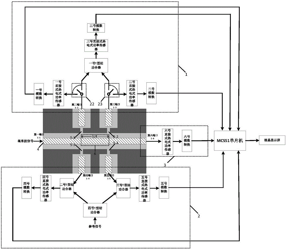
[0034] The sensor part of the silicon-based gap-coupled T-junction direct millimeter-wave signal detection instrument of the present invention is based on a high-resistance Si substrate 7, which consists of a coplanar waveguide transmission line 4 and a No. 1 slot coupling structure 5-1 , No. 2 slot coupling structure 5-2, No. 3 slot coupling structure 5-3, No. 4 slot coupling structure 5-4, phase shifter 6, No. 1 SPDT switch 22, No. 2 SPDT switch 23, one It is composed of T-junction power splitter, three T-junction power combiners and six direct thermoelectric power sensors.

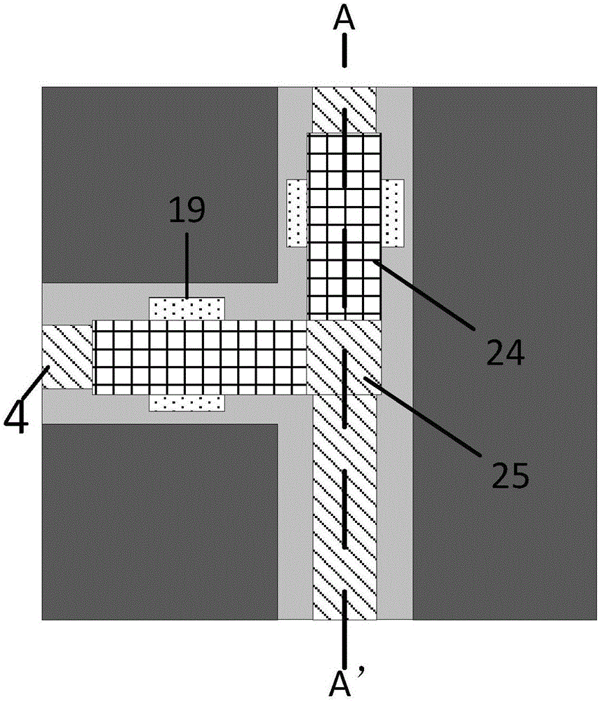
[0035] The structure of the T-junction power divider and the T-junction power combiner is the same, mainly composed of a coplanar waveguide transmission line 4, two fan-shaped defect structures 9 and three air bridges 10, and the fan-shaped defect structure 9 is located at two input The fan-shaped defect ground structure at the port, and the air bridge 10 is a beam...


PUM


Abstract

The invention provides a direct type millimeter wave signal detection instrument of silicon slot coupled T junctions. The instrument comprises three modules, namely a sensor, an analog-digital converter and a liquid crystal display. The sensor comprises a coplane wave guide transmission line, slot coupling structures, a phase shifter, a single-pole double-throw switch, a T junction power divider, a T junction power combiner and a direct thermoelectric power sensor. The whole structure is produced based on a high resistance Si substrate. The two slot coupling structures at the upper side achieve the measuring of frequencies of signals. The two slot coupling structures at the lower side achieve the measuring of phases of the signals. The T junction power divider and the T junction power combiner are mainly composed of coplane wave guide transmission lines, fan shape defected structures and air bridges. The indirect thermoelectric power sensor comprises coplane wave guide transmission lines, thermocouple and blocking capacitor. The analog-digital converter part comprises STM32 and AD620 peripheral circuits. A MCS51 single-chip microcomputer is used for calculating equations. The liquid crystal display part comprises a liquid crystal display screen. The efficiency of the signal detection instrument is substantially increased.

Description

technical field [0001] The invention provides a silicon-based gap-coupled T-junction direct millimeter-wave signal detection instrument, which belongs to the technical field of micro-electro-mechanical systems (MEMS). Background technique [0002] The 21st century is the era of information science and technology. In this era of rapid development, signal detection, as an important science and technology, has been deeply studied, especially in today's military, communication, aerospace and other fields. The detection of various signals is a very important task. A signal has three very important parameters: frequency, phase and power. According to frequency, it can be divided into low frequency signal, high frequency signal and extremely high frequency signal. , where the millimeter-wave signal is an extremely high-frequency signal, which is located in the area where microwaves and far-infrared waves overlap. At present, the detection technology for extremely high-frequency mil...

Claims


Application Information

Patent Timeline
Patent Type & Authority Applications(China)
IPC IPC(8): G01R25/00G01R21/02G01R23/02G01R15/00G01R3/00
CPCG01R3/00G01R15/00G01R21/02G01R23/02G01R25/00
Inventor 廖小平褚晨蕾
Owner SOUTHEAST UNIV
Why Eureka
Try Eureka