Method and device for testing FPGA interconnection line
A test method and interconnection line technology, applied in the field of FPGA test, can solve problems such as low efficiency, achieve the effect of simplifying test operation and improving test efficiency
- Summary
- Abstract
- Description
- Claims
- Application Information
AI Technical Summary
Problems solved by technology
Method used
Image

Examples
Embodiment 1
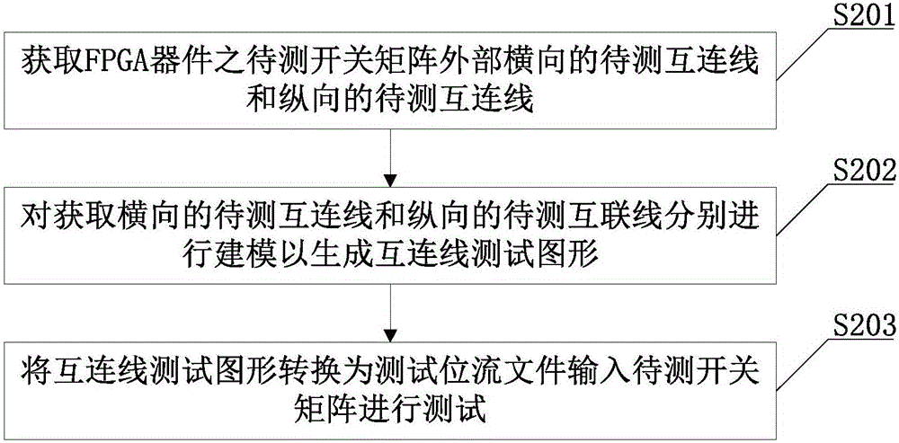
[0053] see figure 2 As shown, the FPGA interconnection testing method provided in this embodiment includes:
[0054] S201: Obtain the horizontal interconnection lines to be tested and the vertical interconnection lines to be tested outside the switch matrix to be tested of the FPGA device.
[0055] In this embodiment, different types of interconnection lines to be tested can be tested separately, and the test method in this embodiment is applicable to any type of interconnection line test; the horizontal interconnection line to be tested in this embodiment refers to The interconnection lines to be tested on the upper and lower sides of the switch matrix; the vertical interconnection lines refer to the interconnection lines to be tested on the left and right sides of the switch matrix.
[0056] S202: Obtaining a horizontal interconnection line to be tested and a vertical interconnection line to be tested are respectively modeled to generate an interconnection line test patter...
Embodiment 2
[0091] The present embodiment provides a kind of FPGA interconnection testing device, see Figure 4 shown, including:
[0092] The interconnection line acquisition module 41 is used to obtain the horizontal interconnection line to be tested and the vertical interconnection line to be tested outside the switch matrix to be tested of the FPGA device; , the interconnection lines to be tested on the lower two sides; the vertical interconnection lines refer to the interconnection lines to be tested on the left and right sides of the switch matrix.
[0093] The test pattern generation module 42 is used to model the horizontal interconnection line to be tested and the vertical interconnection line to be tested respectively to generate an interconnection line test pattern. The test pattern generation module 42 models the horizontal interconnection line to be tested and the vertical interconnection line to be tested respectively, that is, models the horizontal interconnection line to ...
Embodiment 3
[0110] This embodiment proposes that the vertical and horizontal decomposition model of the FPGA interconnection is universal, and does not target any FPGA device, and does not require a special unit structure, as long as the design of the interconnection satisfies the distribution in the vertical and horizontal directions. Currently, any FPGA device on the market has a two-wire structure. Therefore, for ease of understanding, this embodiment uses a representative two-wire structure as an example to illustrate the vertical and horizontal decomposition model of interconnection lines. Such as Figure 5-1 and Figure 5-2 As shown, the longitudinal two-long line and the horizontal two-long line are modeled separately. Figure 5-1 and Figure 5-2 In , the vertical and horizontal decomposition wiring model is an abstraction of the physical connection of the internal interconnection lines of the FPGA device. Regardless of whether it is a horizontal interconnection line or a vertic...
PUM
 Abstract
Description
Claims
Application Information
 - Generate Ideas
- Intellectual Property
- Life Sciences
- Materials
- Tech Scout
- Unparalleled Data Quality
- Higher Quality Content
- 60% Fewer Hallucinations
Browse by: Latest US Patents, China's latest patents, Technical Efficacy Thesaurus, Application Domain, Technology Topic, Popular Technical Reports.
© 2025 PatSnap. All rights reserved.Legal|Privacy policy|Modern Slavery Act Transparency Statement|Sitemap|About US| Contact US: help@patsnap.com