
High-efficiency multi-component seismic data true amplitude migration imaging method

A technology of migration imaging and seismic data, applied in the field of geophysical exploration, can solve problems such as changes in wave field amplitude and phase information, changes in wave field dynamics, elastic waves, and pre-stack depth migration of seismic data.

Active Publication Date: 2017-06-13
CHINA UNIV OF PETROLEUM (EAST CHINA)
View PDF11 Cites 4 Cited by
  • Summary
  • Abstract
  • Description
  • Claims
  • Application Information

AI Technical Summary

Problems solved by technology

However, elastic wave reverse time migration still has many disadvantages, such as: severe migration artifacts caused by longitudinal and shear wave crosstalk, destructive interference in the migration profile caused by shear wave polarity reversal, unreliable amplitude of the migration profile, partial The resolution of the shift profile is low, and the calculation efficiency of the migration algorithm is low. In addition, if the longitudinal and transverse wave separation technology is applied, the amplitude and phase information of the wave field will change, and the dynamic characteristics of the wave field will be changed.
These problems make elastic wave reverse time migration difficult to be applied to prestack depth migration of actual multi-component seismic data

Method used


Image

  • High-efficiency multi-component seismic data true amplitude migration imaging method
  • High-efficiency multi-component seismic data true amplitude migration imaging method
  • High-efficiency multi-component seismic data true amplitude migration imaging method

Examples


example 1

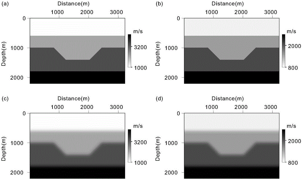
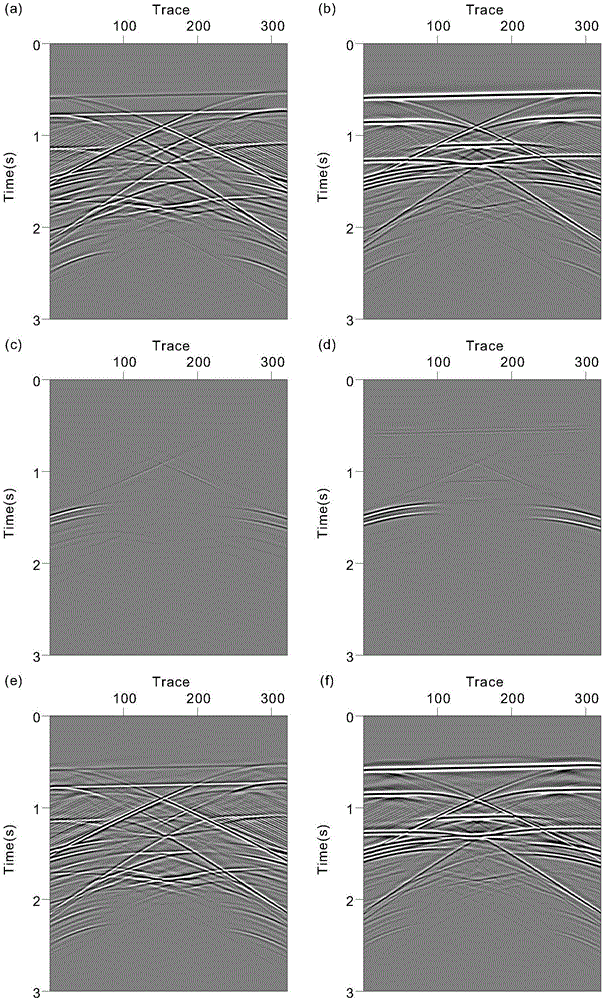
[0154] figure 2 is a two-dimensional depression model diagram; where, figure 2 (a) is the longitudinal wave velocity model; figure 2 (b) is the shear wave velocity model; figure 2 (c) is the background P-wave velocity model; figure 2 (d) is the background shear wave velocity model. Set 21 ray parameters on this model, the initial ray parameter p=-117μs / m, the ray parameter interval is p=15μs / m, the seismic source used is the explosion source, the source wavelet is set as the Lake wavelet, and the main frequency is 20 Hz. image 3 is the encoded shot set after cutting off the direct wave, and the corresponding ray parameter p=0μs / m: where, image 3 (a) is the horizontal component of the coded observation record; image 3 (b) is the vertical component of the coded observation record; image 3 (c) is the initial de-migration record horizontal component of the encoding that utilizes the method of the present invention to gain; image 3 (d) is the initial de-migration ...

example 2

[0156] Figure 5 is the Marmousi-ii model: where, Figure 5 (a) is the longitudinal wave velocity model; Figure 5 (b) is the shear wave velocity model; Figure 5 (c) is the background P-wave velocity model; Figure 5 (d) is the background shear wave velocity model. This model is one of the international standard models to verify the imaging effects of various migration methods. Set 31 ray parameters on this model, the initial ray parameter p=-333μs / m, the ray parameter interval is p=20μs / m, the seismic source used is the explosion source, the source wavelet is set as the Lake wavelet, and the main frequency is 15 Hz. Image 6 yes Figure 5 The multi-shot stacked migration section of the Marmousi-ii model shown: where, Image 6 (a) is the I obtained by the traditional method α profile; Image 6 (b) is the I obtained by the traditional method β profile; Image 6 (c) is the I obtained by utilizing the method of the present invention α profile; Image 6 (d) is the I ...

example 3

[0158] Figure 7 is the SEG / EAGE Salt model: where, Figure 7 (a) is the longitudinal wave velocity model; Figure 7 (b) is the shear wave velocity model; Figure 7 (c) is the background P-wave velocity model; Figure 7 (d) is the background shear wave velocity model. This model is one of the international standard salt dome models to verify the imaging effects of various migration methods. Set 21 ray parameters on this model, the initial ray parameter p=-333μs / m, the ray parameter interval is p=30μs / m, the seismic source used is the explosion source, the source wavelet is set as the Lake wavelet, and the main frequency is 15 Hz. Figure 8 yes Figure 7 The multi-shot stacked migration section of the SEG / EAGESalt model shown: where, Figure 8 (a) is the I obtained by the traditional method α profile; Figure 8 (b) is the I obtained by the traditional method β profile; Figure 8 (c) is the I obtained by utilizing the method of the present invention α profile; Figure...


PUM


Abstract

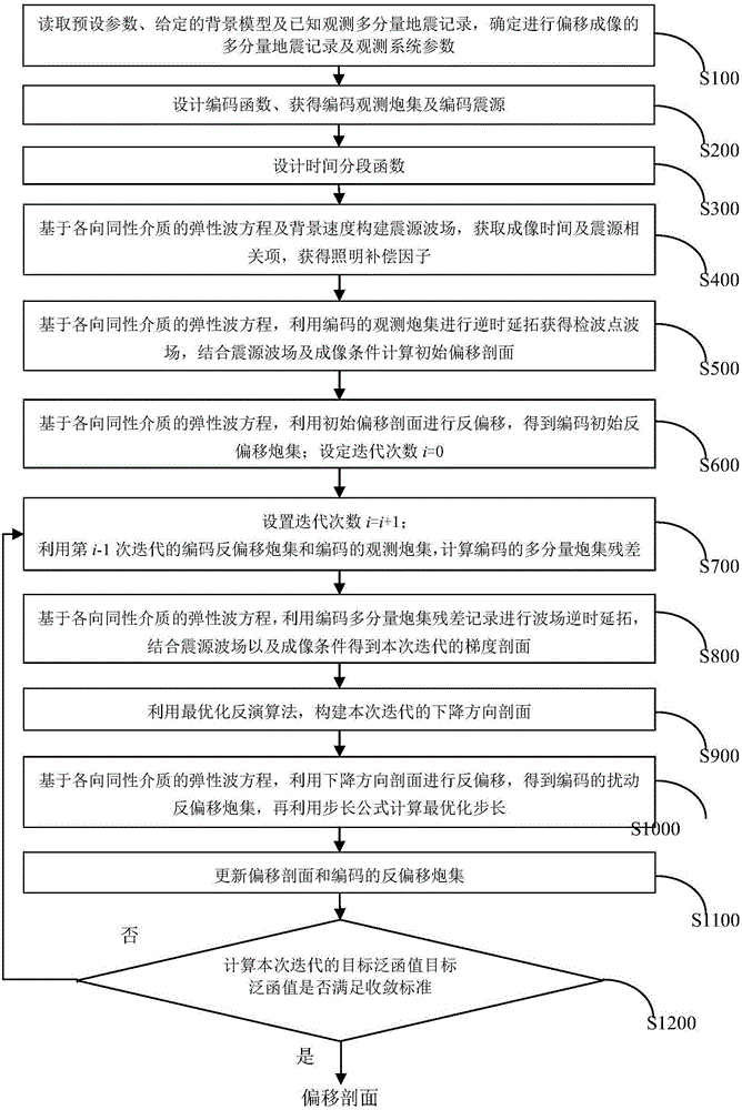
A high-efficiency multi-component seismic data true amplitude migration imaging method is applied to the technical field of multi-component seismic data treatment. The method is an improvement on the basis of an elastic wave reverse time migration method and is characterized by directly taking multi-component seismic data as input and taking measures such as encryption algorithms and segmented imaging to achieve inversion-based elastic wave reverse time migration under an inversion framework. The high-efficiency multi-component seismic data true amplitude migration imaging method introduces encryption, time segmentation and inversion into elastic wave reverse time migration, thereby, compared with normal elastic wave reverse time migration, acquiring high-precision and amplitude-preserved pre-stack depth migration sections and achieving high algorithm efficiency. The high-efficiency multi-component seismic data true amplitude migration imaging method can completely maintain the vector features, the amplitudes and the phase features of longitudinal and transverse waves as well as fidelity of migration sections, effectively eliminate migration pseudo phenomena caused by crosstalk of the longitudinal and transverse waves, improve the imaging precision, effectively reduce the memory space of elastic wave reverse time migration and improve the computational efficiency.

Description

technical field [0001] The invention belongs to the field of geophysical exploration and relates to pre-stack migration imaging processing of multi-component seismic data, in particular to a high-efficiency, low-storage multi-component seismic data true amplitude migration imaging method. Background technique [0002] Most of the traditional oil and gas exploration is based on the P-wave exploration method. This method believes that only P-waves exist in the underground medium. However, the actual wave field propagating in the underground medium includes not only P-waves, but also S-waves and converted waves. Seismic wavefields are elastic wavefields. Multi-component seismic data naturally contain multiple wave types such as longitudinal wave, shear wave and converted wave. Using traditional single-component seismic data processing methods to process multi-component seismic data will inevitably have large errors, and even lead to wrong processing results. Prestack depth mig...

Claims


Application Information

Patent Timeline
IPC IPC(8): G01V1/28
CPCG01V1/28
Inventor 谷丙洛李振春
Owner CHINA UNIV OF PETROLEUM (EAST CHINA)
Learn More