
Optical athermalization, high-pixel, high-illumination and low-cost heat imaging system

A heat-absorbing, high-pixel technology, applied in the field of optical systems, can solve problems such as large temperature coefficient of refractive index, high processing cost, and large thermal difference of the lens, and achieve the effect of reducing complexity, reducing processing cost, and stabilizing resolution

Inactive Publication Date: 2017-06-13
UNION OPTECH
View PDF11 Cites 2 Cited by
  • Summary
  • Abstract
  • Description
  • Claims
  • Application Information

AI Technical Summary

Problems solved by technology

[0002] At present, the lenses used in monitoring and vehicle-mounted systems in the field of view generally have such shortcomings: large thermal difference of the lens, high cost, etc.
In order to achieve adiabatic difference and high resolution, germanium or zinc sulfide lenses are generally used for imaging. These two materials are expensive. In addition, the current aspheric lenses made of germanium and zinc sulfide can only be processed by turning, and the processing cost is high. Furthermore, the temperature coefficient of the refractive index of these two materials is large, and the heat difference is large, so a mechanical heat dissipation difference is required, and additional mechanical devices are added, which again increases the cost

Method used


Image

  • Optical athermalization, high-pixel, high-illumination and low-cost heat imaging system
  • Optical athermalization, high-pixel, high-illumination and low-cost heat imaging system
  • Optical athermalization, high-pixel, high-illumination and low-cost heat imaging system

Examples


Embodiment Construction

[0020] Below in conjunction with accompanying drawing, the present invention is described in further detail:

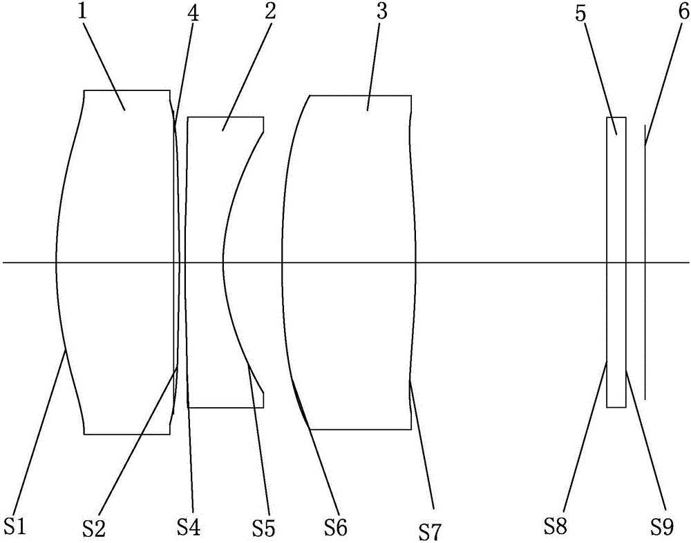
[0021] Such as figure 1 As shown, an optical athermalization, high pixel, high illuminance, low-cost infrared thermal imaging system, from the object side to the image side sequentially includes: a first lens 1, a diaphragm 4, a second lens 2, a third lens 3 And the photosensitive chip 6, the first lens 1, the second lens 2, and the third lens 3 are all aspheric lenses of chalcogenide glass, and a protective window glass 5 is arranged between the third lens 3 and the photosensitive chip 6.

[0022] Such as figure 1 As shown, in this embodiment, the focal lengths of the first lens 1 and the third lens 3 are positive, and the focal lengths of the second lens 2 are negative.

[0023] Such as figure 1 As shown, in this embodiment, the aspheric surface types of the first lens 1, the second lens 2 and the third lens 3 satisfy the equation:

[0024]

[0025] In the ab...


PUM

PropertyMeasurementUnit
Horizontal widthaaaaaaaaaa

Abstract

The invention discloses an optical athermalization, high-pixel, high-illumination and low-cost heat imaging system. The optical athermalization, high-pixel, high-illumination and low-cost heat imaging system is sequentially provided with a first lens, a diaphragm, a second lens, a third lens and a light sensing chip from an object side to an image side, wherein the first lens, the second lens and the third lens are chalcogenide glass non-spherical surface lenses; focal distances of the first lens and the third lens are positive; and the focal distance of the second lens is negative. According to the optical athermalization, high-pixel, high-illumination and low-cost heat imaging system, low-price chalcogenide glass is adopted and the material can be molded by die pressing, so that the processing cost can be reduced; the thermal refractive index coefficient of the chalcogenide glass is only 1 / 10 of a germanium crystal material, so that the change of the resolving power of a system composed of the chalcogenide glass lenses along with temperature is relatively small, and stable resolving power and no focus shift can be realized through optical athermalization; and meanwhile, the complexity of the structure is reduced and the cost is reduced. The lens is designed by adopting wide spectrums with the lengths of 7.5 microns to 14 microns at the ratio of 1 to 1 to 1 to 1, and has extremely good image sharpness at a far-infrared band; and a whole picture can be clearly imaged.

Description

【Technical field】 [0001] The invention relates to an optical system, in particular to an optical athermalization, high-pixel, high-illuminance, and low-cost infrared thermal imaging system for monitoring and vehicle-mounted systems. 【Background technique】 [0002] At present, the lenses used in monitoring and vehicle-mounted systems in the field of view generally have such shortcomings: large thermal difference of the lens, high cost, etc. In order to achieve adiabatic and high-resolution images, germanium or zinc sulfide lenses are generally used for imaging. These two materials are expensive. In addition, the current aspheric lenses made of germanium and zinc sulfide can only be processed by turning, and the processing cost is high. Furthermore, these two materials have a large temperature coefficient of refraction index and a large thermal difference, requiring the use of a mechanical adiabatic difference, adding an additional mechanical device, which again increases the ...

Claims


Application Information

Patent Timeline
IPC IPC(8): G02B13/18G02B13/14G02B1/00
CPCG02B13/14G02B13/18G02B1/00
Inventor 罗吉祥肖明志陈安科邹艳华张艺婷
Owner UNION OPTECH
Learn More