
Image pickup objective lens optical system used for looking inside

A technology of optical system and objective lens, which is applied in the field of objective lens optical system, can solve the problems of dirty chip, small structure, easy to touch the chip, etc., and achieve the effect of optimizing image plane curvature, realizing wide angle, and suppressing off-axis phase difference

Active Publication Date: 2017-06-13
东莞市宇光光电科技有限公司
View PDF9 Cites 13 Cited by
  • Summary
  • Abstract
  • Description
  • Claims
  • Application Information

AI Technical Summary

Problems solved by technology

[0004] Chinese patent document CN201945733U discloses an objective lens for an endoscope, comprising a first objective lens, a second objective lens, a third objective lens and a fourth objective lens arranged in sequence, the first objective lens is a meniscus negative lens, and the second objective lens is a meniscus lens. Moon positive lens, the third objective lens is a biconvex positive lens, the fourth objective lens is a convex plano positive lens, the convex surface of the fourth objective lens is connected with the third objective lens, and a diaphragm is arranged between the second objective lens and the third objective lens , the structure is small, the field of view is large, and the amount of light can be effectively improved, but the back intercept is too small, it is easy to touch the chip, causing the chip to be dirty, affecting the shooting effect, and difficult to install

Method used


Image

  • Image pickup objective lens optical system used for looking inside
  • Image pickup objective lens optical system used for looking inside
  • Image pickup objective lens optical system used for looking inside

Examples


Embodiment 1

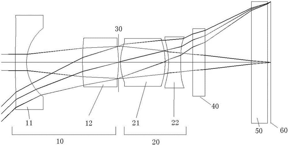
[0090] Please refer to figure 1 , a camera objective lens optical system for endoscopy includes a first lens group 10 with negative refractive power, a diaphragm 30, a second lens group 20 with positive refractive power, an optical filter 40, Flat glass 50 and photosensitive surface 60 of the chip. The optical filter 40 is mainly used to cut off a specific wavelength, and the flat glass 50 is mainly used to protect the photosensitive surface 60 of the chip.

[0091] Described first lens group 10 is made of the first lens 11 with negative refractive power and the second lens 12 with positive refractive power, and the object side surface of described first lens 11 is convex surface, and image side surface is concave surface, and the second lens The object side and the image side of 12 are both convex, and the second lens group 20 is composed of a third lens 21 with positive refractive power and a fourth lens 22 with negative refractive power, and the object side and image side ...

Embodiment 2

[0098] Please refer to image 3 , a camera objective lens optical system for endoscopy includes a first lens group 10 with negative refractive power, a diaphragm 30, a second lens group 20 with positive refractive power, an optical filter 40, Flat glass 50 and photosensitive surface 60 of the chip. The optical filter 40 is mainly used to cut off a specific wavelength, and the flat glass 50 is mainly used to protect the photosensitive surface 60 of the chip.

[0099] Described first lens group 10 is made of the first lens 11 with negative refractive power and the second lens 12 with positive refractive power, and the object side surface of described first lens 11 is convex surface, and image side surface is concave surface, and the second lens The object side and the image side of 12 are both convex, and the second lens group 20 is composed of a third lens 21 with positive refractive power and a fourth lens 22 with negative refractive power, and the object side and image side ...

Embodiment 3

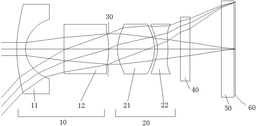
[0106] Please refer to Figure 5 , a camera objective lens optical system for endoscopy includes a first lens group 10 with negative refractive power, a diaphragm 30, a second lens group 20 with positive refractive power, an optical filter 40, Flat glass 50 and photosensitive surface 60 of the chip. The optical filter 40 is mainly used to cut off a specific wavelength, and the flat glass 50 is mainly used to protect the photosensitive surface 60 of the chip.

[0107] Described first lens group 10 is made of the first lens 11 with negative refractive power and the second lens 12 with positive refractive power, and the object side and image side of described first lens 11 are concave surfaces, and the second lens 12 Both the object side and the image side are convex, and the second lens group 20 is composed of a third lens 21 with positive refractive power and a fourth lens 22 with negative refractive power, and the object side and the image side of the third lens 21 are convex...


PUM

PropertyMeasurementUnit
Caliberaaaaaaaaaa

Abstract

The invention discloses an image pickup objective lens optical system used for looking inside. The system includes a first lens unit, a diaphragm and a second lens unit arranged successively from an object side to an image side. The first lens unit includes a first lens and a second lens. The second lens unit includes a third lens and a fourth lens. Besides, a following conditional expression is met. f / H(L1r1)<1.8; H(L1r1) / IMH<0.8; TTL / f<5.5; BF / f>1.2, wherein f indicates the focal length of the image pickup objective lens optical system used for looking inside; H(L1r1) indicates a length of main light beams corresponding to the maximal image height when the main light beams pass through a face on the object side of the first lens unit in regular observation; IMH indicates the maximal image height on a corresponding chip light sensing face in regular observation; TTL indicates the distance between a face of the object side of the first lens in an optical axis and the chip light sensing face; and BF indicates the distance between a face of the image side of the fourth lens in the optical axis to the chip light sensing face. The image pickup objective lens optical system used for looking inside has characteristics of small diameter, wide view angle and installation convenience.

Description

technical field [0001] The invention relates to an objective optical system, in particular to an endoscope imaging objective optical system. Background technique [0002] Endoscope is a kind of medical optical instrument, which is sent into the body from the outside through the natural cavity of the human body to check the diseases in the body. Scanning the film greatly improves the accuracy of cancer diagnosis, and can carry out some minimally invasive surgical treatment. [0003] In order to alleviate the pain of patients to a greater extent, shorten the recovery time after surgery, reduce the work of doctors, and improve the diagnostic level of visualization and scientific data judgment, it is necessary to further reduce the endoscopic camera system and improve its imaging shooting effect Therefore, it is a technical subject to study and use a larger field of view, smaller and clearer objective lens optical system for endoscopic imaging. [0004] Chinese patent document...

Claims


Application Information

Patent Timeline
IPC IPC(8): G02B23/24G02B13/00G02B13/18G02B13/06A61B1/00
CPCA61B1/00163G02B13/0015G02B13/004G02B13/06G02B23/243
Inventor 蒋千年涂小芹涂孝涛陈霞光
Owner 东莞市宇光光电科技有限公司
Features
  • Generate Ideas
  • Intellectual Property
  • Life Sciences
  • Materials
  • Tech Scout
  • Unparalleled Data Quality
  • Higher Quality Content
  • 60% Fewer Hallucinations
Learn More