Variable speed pumped storage unit water pump working condition self-start control device and method thereof

A pumped storage and unit technology, applied in the control of electromechanical transmission, motor generator control, electronic commutation motor control, etc., can solve the problems of complex starting process, shock hazards of the unit and power grid, and high price, and achieve good efficiency. Stickiness and estimation accuracy, overcoming the problem of inaccurate orientation, and improving the success rate

Inactive Publication Date: 2017-06-13
NARI TECH CO LTD +4
View PDF2 Cites 16 Cited by
  • Summary
  • Abstract
  • Description
  • Claims
  • Application Information

AI Technical Summary

Problems solved by technology

[0004] The traditional asynchronous starting or motor starting current is getting bigger and bigger, which will cause huge shock hazards to both the unit and the power grid, making the mechanical shock, thermal shock and instantaneous voltage drop of the power grid that the unit itself bears exceed the limit
Although the synchronous starting method overcomes the impact on the power grid, it has the problem of long starting time and cannot start the last motor; the semi-synchronous starting method combines the characteristics of asynchronous starting and synchronous starting, which has no impact on the system and less energy loss. Small, but the starting process is very complicated, and the capacity of the starter unit must be greater than 80% of the motor capacity
, with the rapid development and maturity of modern power electronics technology, the method of starting the pumped storage unit through the static frequency converter has gradually occupied a dominant position, but it needs to be equipped with expensive static frequency converter starting equipment

Method used


Image

  • Variable speed pumped storage unit water pump working condition self-start control device and method thereof
  • Variable speed pumped storage unit water pump working condition self-start control device and method thereof
  • Variable speed pumped storage unit water pump working condition self-start control device and method thereof

Examples


Embodiment Construction

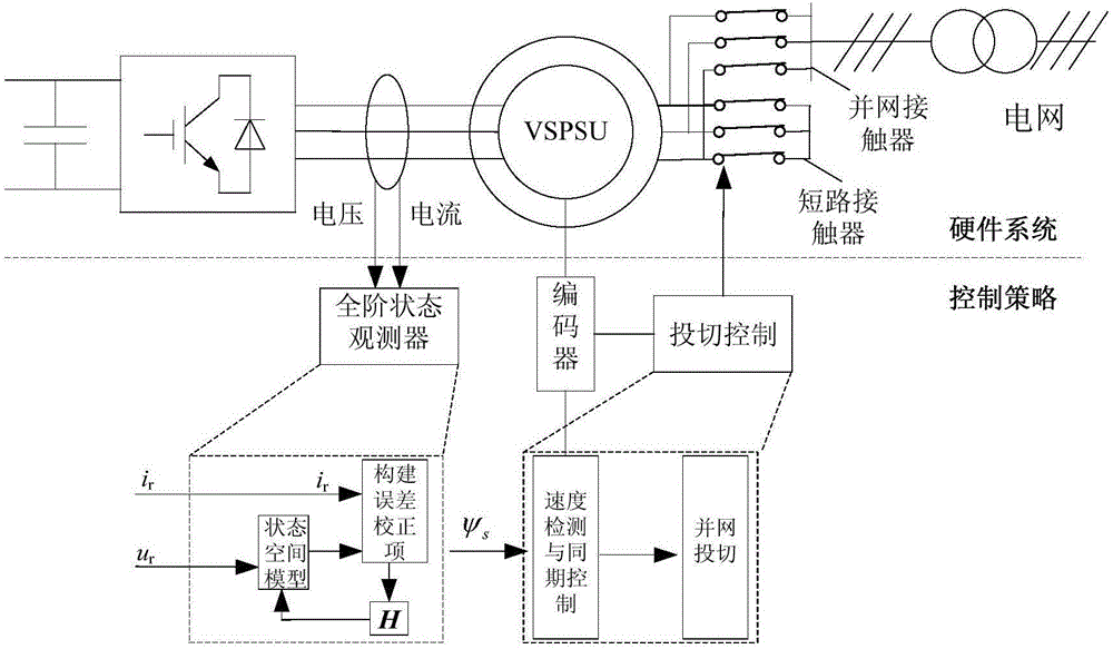
[0039] The invention provides a self-starting control device for pump working conditions of a pumped-storage variable-speed unit, which includes an encoder connected to the pumped-storage variable-speed unit, and connected to the stator of the pumped-storage variable-speed unit for short-circuiting the pumped-storage variable speed The short-circuit contactor of the stator of the unit, and the grid-connected contactor connected to the pumped-storage variable-speed unit and used to control the synchronization of the pumped-storage variable-speed unit;

[0040] Further, the encoder is used to detect the rotor speed of the variable-speed unit and to operate the grid-connected synchronization control of the variable-speed unit.

[0041] A self-starting control method for pump working conditions of a pumped-storage variable speed unit, the method includes the following steps:

[0042] Step 1: Stator short-circuit double closed-loop control; short-circuit the stator through a short-circuit...


PUM


Abstract

The invention provides a variable speed pumped storage unit (Variable Speed Pumped Storage Units, VSPSU) water pump working condition self-start control device and a method thereof. The stator winding is short-circuited, the rotor current is controlled through its own alternate current excitation device, so as to control the rotor magnetic field, drag torque is generated by the interaction between the stator and the rotor magnetic field, to drive the rotor to start. A full order state observation device is built, the precise stator magnetic chain location is estimated, the decoupling control of rotor current is achieved, and rotor speed is controlled; after the rotor speed reaches a preset value, the corresponding period grid-connected control is conducted, the decline of stator current is controlled; after the rotor voltage amplitude, the frequency and the phase meet the requirements, stator sides and a grid contact device are switched; the scheme does not need the static frequency device and other additional starting devices, while having a high degree of control precision and reliability.

Description

Technical field [0001] The invention relates to a self-starting control method of a pumped-storage unit under pumping conditions, and is suitable for a variable-speed constant-frequency pumped-storage unit using a double-fed motor. Background technique [0002] At present, the traditional constant-speed and constant-frequency power generation dominates hydropower, and synchronous generators are generally the mainstay. Most of its excitation adjustment adopts DC excitation, and the reactive power of the synchronous generator is adjusted by adjusting the excitation current to meet the requirements of the power grid. Since it is a constant-speed and constant-frequency power generation, there is no relative movement between the magnetic field and the rotor. The rotor speed is determined by the frequency of the grid, that is, the generator must run at a constant speed under any circumstances. However, unlike traditional hydropower stations, pumped-storage power stations change the wa...

Claims


Application Information

Patent Timeline
Patent Type & Authority Applications(China)
IPC IPC(8): H02P21/34H02P21/18H02J3/40
CPCH02J3/40
Inventor 纪历周百灵邵宜祥石磊周敏王舒朱丹王琴
Owner NARI TECH CO LTD
Why Eureka
Try Eureka