Pulse density modulation method and pulse density value signal conversion circuit
A technology of pulse density modulation and pulse density, applied in the direction of analog conversion, pulse processing, code conversion, etc., can solve the problem of uneven output waveform
- Summary
- Abstract
- Description
- Claims
- Application Information
AI Technical Summary
Problems solved by technology
Method used
Image
Examples
Embodiment 1
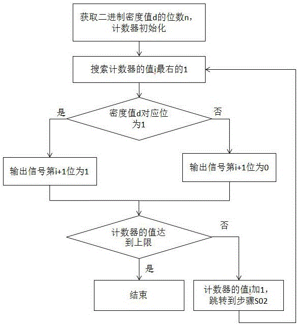
[0057] Embodiment 1: a kind of pulse density modulation method of this embodiment, such as figure 1 shown, including the following steps:
[0058] S01, obtain the digit n of the binary density value d, set the digit of the counter to n, and the initial value of the counter is 0 or 1; the number in the counter is a binary number;
[0059] S02. Search for the rightmost 1: obtain the digit j of the rightmost 1 of the current value i of the counter and count from right to left; the minimum value of j is 1;
[0060] S03. Determine whether the corresponding bits are equal: if the jth bit of d from left to right is 1, the signal bit output in this cycle is 1; if the jth bit of d from left to right is 0, then the signal output in this cycle bit is 0;
[0061] S04, adding 1 to the value i of the counter, entering the next cycle, and jumping to step S02.
[0062] The sequence formed by the signal bits output in each cycle is the output signal, which is the output of this scheme. Eac...
Embodiment 2
[0124] Embodiment 2: a kind of pulse density modulation method of this embodiment, comprises the following steps:
[0125] S01, obtain the digit n of the binary density value d, set the digit of the counter to n, and the initial value of the counter is 0;
[0126] S02. Search for the rightmost 1: obtain the digit j of the rightmost 1 of the current value i of the counter and count from right to left;
[0127] S03. Determine whether the corresponding bits are equal: if the jth bit of d from left to right is 1, then the i-th bit of the output signal is 1; if the j-th bit of d from left to right is 0, then the i-th bit of the output signal is 0;
[0128] S04, judging whether the value of the counter reaches the upper limit, if yes, then end, otherwise enter step S05;
[0129] S05; add 1 to the value i of the counter, and jump to step S02.
[0130] In step S02, the search for the rightmost 1 is obtained through a loop test from left to right or from right to left;
[0131] In ...
Embodiment 3
[0134] Embodiment 3: a kind of pulse density modulation method of this embodiment, comprises the following steps:
[0135] S01, obtain the digit n of the binary density value d, set the digit of the counter to n, and the initial value of the counter is 0;
[0136] S02, search for the rightmost 1, and judge whether the corresponding bits are equal;
[0137] S03, determine whether the value of the counter reaches the upper limit, if yes, then end, otherwise enter step S04;
[0138] S04; add 1 to the value i of the counter, and jump to step S02.
[0139] Step S02 is specifically:
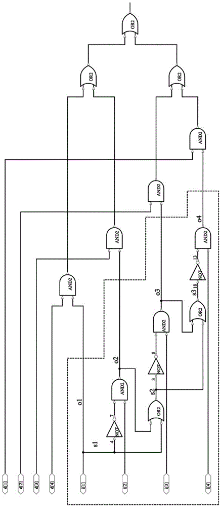
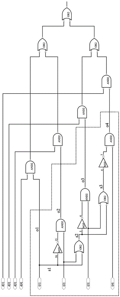
[0140] S11. Reverse the density value d in bit order to obtain D; the bit order inversion here is to put the original first bit into the last bit, and the original second bit into the penultimate bit, and so on; set d is 0011, and D is 1100; n is 4, and i is set to 0100;
[0141] S12, subtract one from the count value i, and then XOR with the original i to obtain k; when i is 0, set the i+1th bit o...
PUM
 Abstract
Description
Claims
Application Information
 - R&D
- Intellectual Property
- Life Sciences
- Materials
- Tech Scout
- Unparalleled Data Quality
- Higher Quality Content
- 60% Fewer Hallucinations
Browse by: Latest US Patents, China's latest patents, Technical Efficacy Thesaurus, Application Domain, Technology Topic, Popular Technical Reports.
© 2025 PatSnap. All rights reserved.Legal|Privacy policy|Modern Slavery Act Transparency Statement|Sitemap|About US| Contact US: help@patsnap.com


