
Optical Receiver Antenna for Angle Diversity Filled Compound Parabolic Concentrator

An optical receiving antenna and compound paraboloid technology, applied in optics, condenser mirrors, optical elements, etc., can solve the problems of good focusing effect, small field of view of optical antenna, difficulty in applying VLC system, etc., to increase receiving energy and improve receiving field of view angle, the effect of reducing the spot size

Inactive Publication Date: 2019-04-09
BEIJING INSTITUTE OF TECHNOLOGYGY
View PDF4 Cites 0 Cited by
  • Summary
  • Abstract
  • Description
  • Claims
  • Application Information

AI Technical Summary

Problems solved by technology

[0003] Most of the traditional optical antennas have a small field of view when the gain is large, and it is difficult to guarantee a good focusing effect when the field of view is large, so it is difficult to apply to the VLC system

Method used

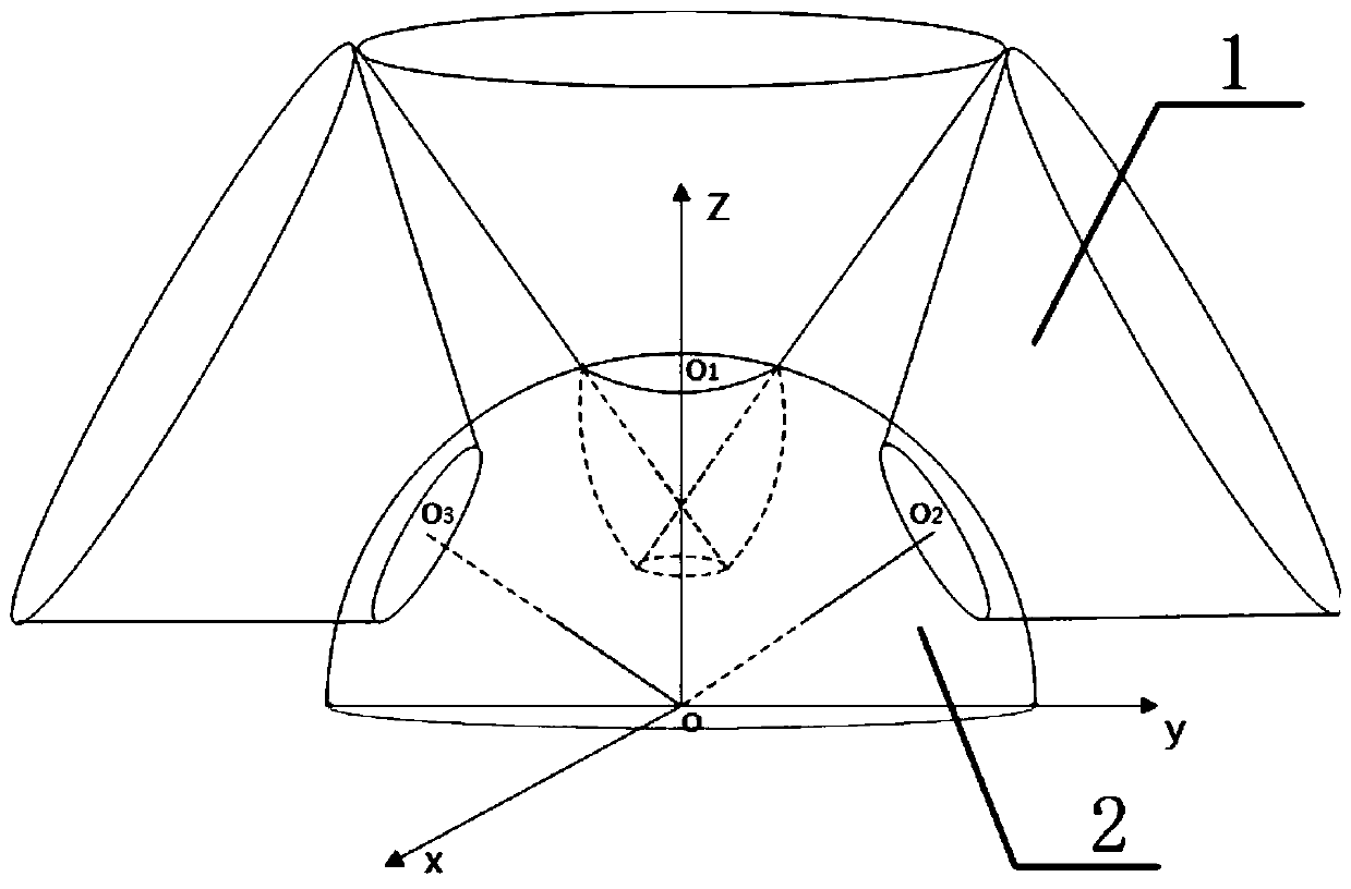
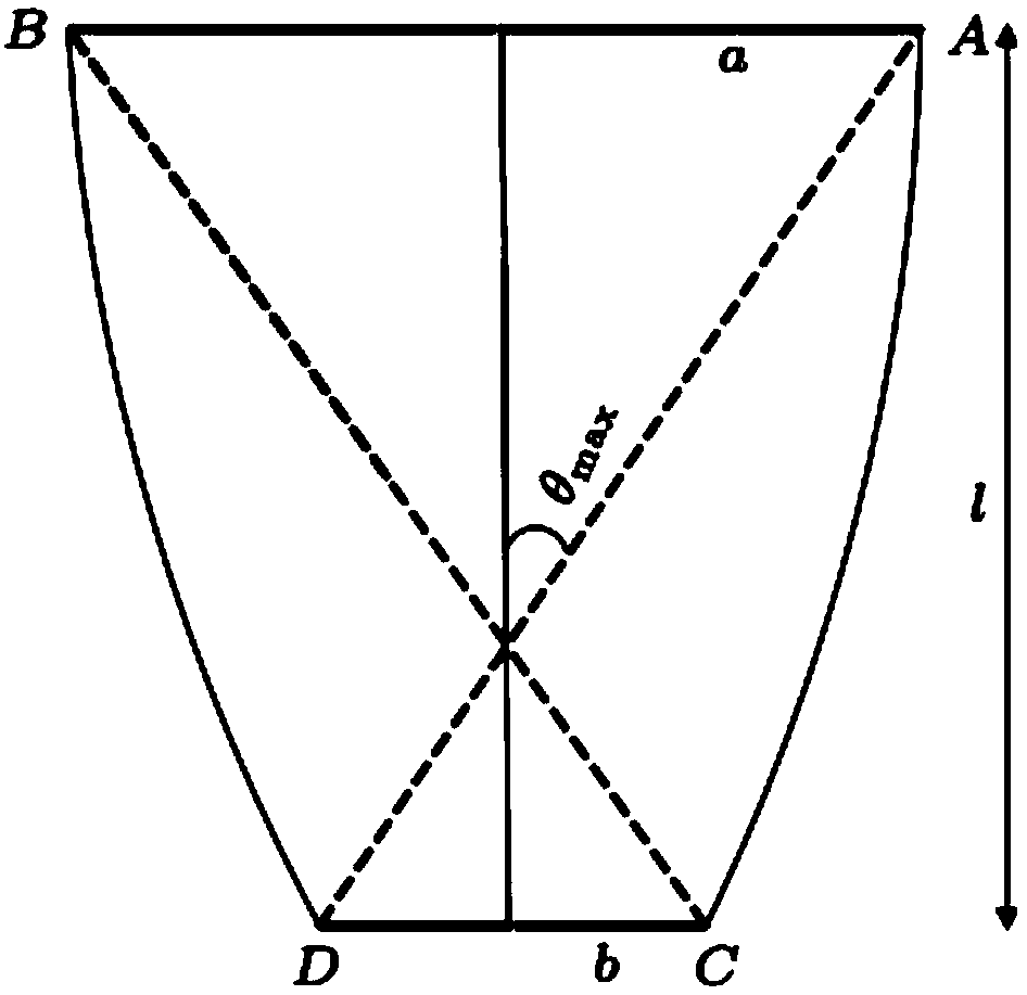
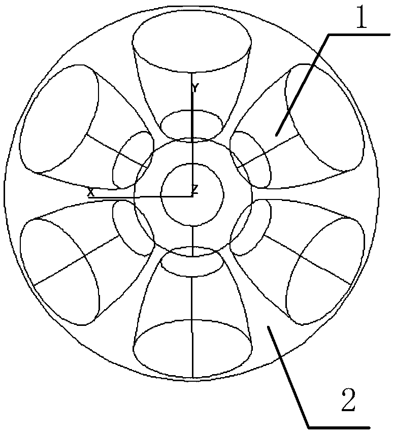

Image

  • Optical Receiver Antenna for Angle Diversity Filled Compound Parabolic Concentrator
  • Optical Receiver Antenna for Angle Diversity Filled Compound Parabolic Concentrator
  • Optical Receiver Antenna for Angle Diversity Filled Compound Parabolic Concentrator

Examples


Embodiment Construction

[0030] The present invention will be described in further detail below in conjunction with the accompanying drawings.

[0031] The invention is designed for wide-field reception of indoor white LED visible light high-speed communication.

[0032] Indoor white light LED communication needs to take into account the lighting function of the system and is limited by the power of a single LED light, so a multi-light source layout with multiple groups of LEDs is required. Under different light source layouts, the requirements for receiving signal angles at various positions in the room are different, so a larger receiving antenna field of view is required.

[0033] In view of the above demand analysis, the present invention provides an optical receiving antenna of an angle-diversity filled compound parabolic concentrator CPC, which uses the compound parabolic concentrator CPC as the basic unit for indoor white LED communication reception. Since the CPC belongs to the non-imaging con...


PUM


Abstract

The present invention discloses an angle diversity-type optical receiving antenna with filled compound parabolic condensers. A whole field of view angle that an angle diversity-type compound parabolic condenser CPC optical antenna can reach is large, and the whole field of view angle can be up to 360 degrees in the horizontal direction, and be up to 180 degrees in the vertical direction. Occurrence of a blind region in the communication can be effectively prevented, CPC units are symmetrically arranged in a hemisphere, and when the optical antenna is placed in any position of a room, a receiving effect cannot be affected. An angle diversity receiving technology is adopted, and the large field of view of the optical antenna is maintained without sacrificing light energy receiving gain of the system. A gradient index lens is adopted, has a light concentrating function, and can effectively reduce the size of the output faculae, improve the receiving energy of a detector per unit area, and improve the receiving gain of the optical receiving antenna; according to different application requirements, the gradient index lenses with different materials and variation laws can fill the CPCs with the same standard, achieving flexibility and variation; and when an optical signal in the same field of view angle is received, the antenna has a smaller size and is smart and convenient.

Description

technical field [0001] The invention relates to receiving antenna technology in the application field of visible light communication, in particular to an angle-diversity optical receiving antenna with a filled compound parabolic concentrator as a basic unit. It is used for large-angle optical signal reception in indoor visible light communication systems using white LEDs as light sources, which can improve the receiving field of view while ensuring the receiving gain. Background technique [0002] Visible Light Communication (Visible Light Communication, VLC) is a new type of wireless optical communication technology based on white light-emitting diodes (LEDs). It does not occupy spectral bandwidth, has no electromagnetic interference, and has both lighting and communication functions. A means of communication with potential for development. The optical receiving antenna of the system is placed in front of the receiver to concentrate as much light energy as possible to the ...

Claims


Application Information

Patent Timeline
Patent Type & Authority Patents(China)
IPC IPC(8): H04B10/116H04B10/67G02B19/00
CPCG02B19/0009G02B19/0085H04B10/116H04B10/67
Inventor 蓝天王岱王云刘品伟倪国强
Owner BEIJING INSTITUTE OF TECHNOLOGYGY
Learn More