

IP layer path selection method, device and system
A technology for selecting devices and paths, which is applied in the field of communications and can solve problems such as affecting IP layer path performance and being unable to provide performance for users
- Summary
- Abstract
- Description
- Claims
- Application Information
AI Technical Summary
Problems solved by technology
Method used
Image

Examples
Embodiment 1
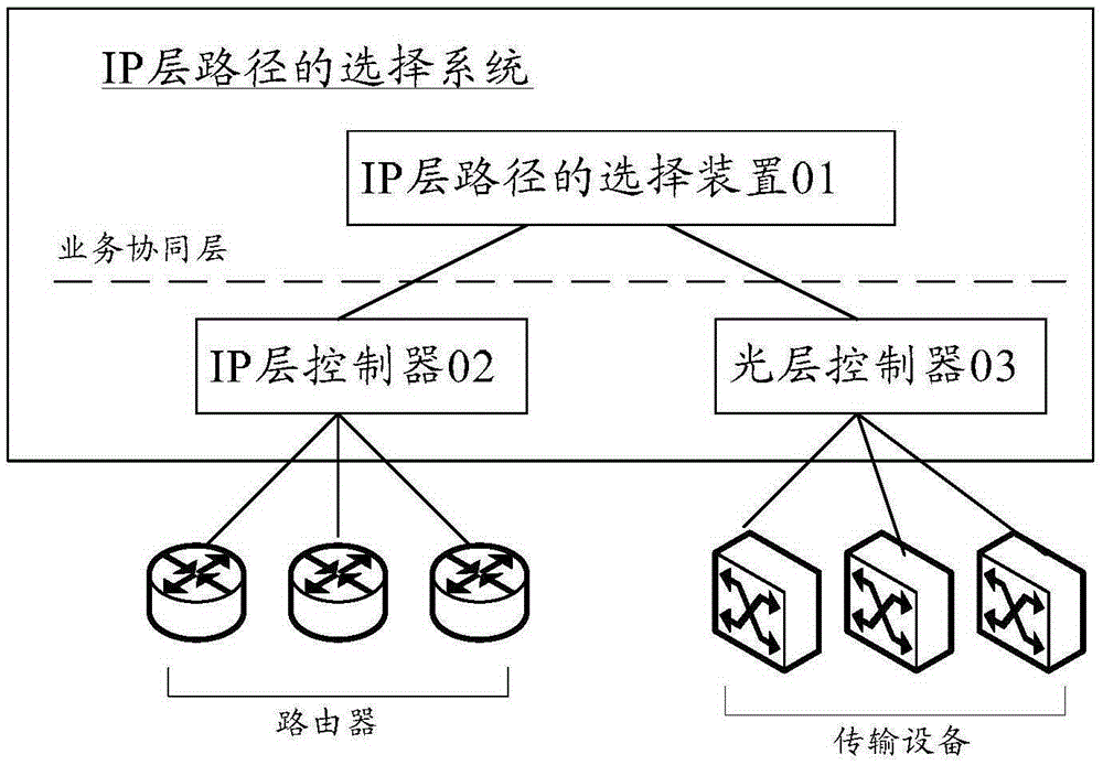
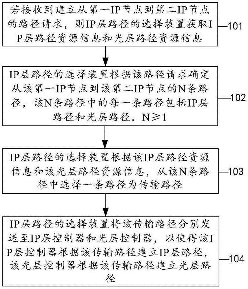
[0039] Embodiments of the present invention provide a method for selecting an IP layer path, such as figure 2 shown, including:
[0040] 101. If a request for establishing a path from a first IP node to a second IP node is received, the device for selecting an IP layer path acquires IP layer path resource information and optical layer path resource information.
[0041] 102. The device for selecting an IP layer path determines N paths from the first IP node to the second IP node according to the path request, each of the N paths includes an IP layer path and an optical layer path, and N≥1 .
[0042] 103. The device for selecting an IP layer path selects one path from the N paths as a transmission path according to the IP layer path resource information and the optical layer path resource information.
[0043] 104. The device for selecting an IP layer path sends the transmission path to the IP layer controller and the optical layer controller respectively, so that the IP lay...
Embodiment 2
[0065] Based on the selection method of the IP layer path described in steps 101-104 in the above-mentioned embodiment 1, the embodiment of the present invention provides a processing method for an optical link failure, such as Figure 4 shown, including:
[0066] 201. If the optical layer controller detects that a failure occurs on the first optical link, send a failure message of the first optical link to the device for selecting an IP layer path.
[0067] 202. The apparatus for selecting an IP layer path determines a first IP link carried on the first optical link.
[0068] 203. The apparatus for selecting an IP layer path determines a link requirement of services on the first IP link on the first IP link.
[0069] 204. The apparatus for selecting an IP layer path re-establishes a second optical link meeting the link requirement at the optical layer, so that the first IP link is changed to be carried by the second optical link.
[0070] 205. If the optical layer does not ...
Embodiment 3
[0080] Based on the above steps 101-104, such as Figure 5 As shown, the device for selecting an IP layer path provided by the embodiment of the present invention can be divided into an acquiring unit 11 , a determining unit 12 , a model selecting unit 13 and a sending unit 14 exemplarily.
[0081] Wherein, the acquiring unit 11 is configured to receive a request for establishing a path from the first IP node to the second IP node; and acquire IP layer path resource information and optical layer path resource information;
[0082] A determination unit 12, configured to determine N paths from the first IP node to the second IP node according to the path request, each of the N paths includes an IP layer path and an optical layer path, N ≥1;
[0083] A selection unit 13, configured to select a path from the N paths determined in the determination unit 12 as a transmission path according to the IP layer path resource information and the optical layer path resource information in ...
PUM
 Abstract
Description
Claims
Application Information