
Pipeline type natural gas condensed liquid rotating flow separator

A cyclone separator and natural gas technology, which is applied in the field of multiphase separation of oil and gas gathering and transportation systems, can solve the problems that the vertical structure cannot be directly installed, affects the separation efficiency of the separator, and energy loss, so as to reduce the probability of crushing and rebound , Conducive to the effect of pressure energy and reducing impact loss

Active Publication Date: 2017-06-20
CHINA UNIV OF PETROLEUM (EAST CHINA)
View PDF5 Cites 19 Cited by
  • Summary
  • Abstract
  • Description
  • Claims
  • Application Information

AI Technical Summary

Problems solved by technology

However, for the incoming flow with high liquid content, the high-speed impact shear of the gas-liquid two-phase in the separator will cause the droplet to break up, cause the entrainment of the gas to the droplet, and affect the separation efficiency of the separator.
A vortex tube type gas-liquid separator disclosed in Chinese invention patent CN105148625A adopts a vertical two-stage centrifugal separation method for gas-liquid separation. The structure cannot be installed directly on the horizontal incoming flow pipeline
Moreover, the internal structure of the cavity is complex, and secondary vortices are easily generated, and the gas is separated by two stages of centrifugation, resulting in a large energy loss

Method used


Image

  • Pipeline type natural gas condensed liquid rotating flow separator
  • Pipeline type natural gas condensed liquid rotating flow separator
  • Pipeline type natural gas condensed liquid rotating flow separator

Examples


Embodiment Construction

[0022] The present invention will be further described below in conjunction with accompanying drawing, but the present invention is not limited to following embodiment.

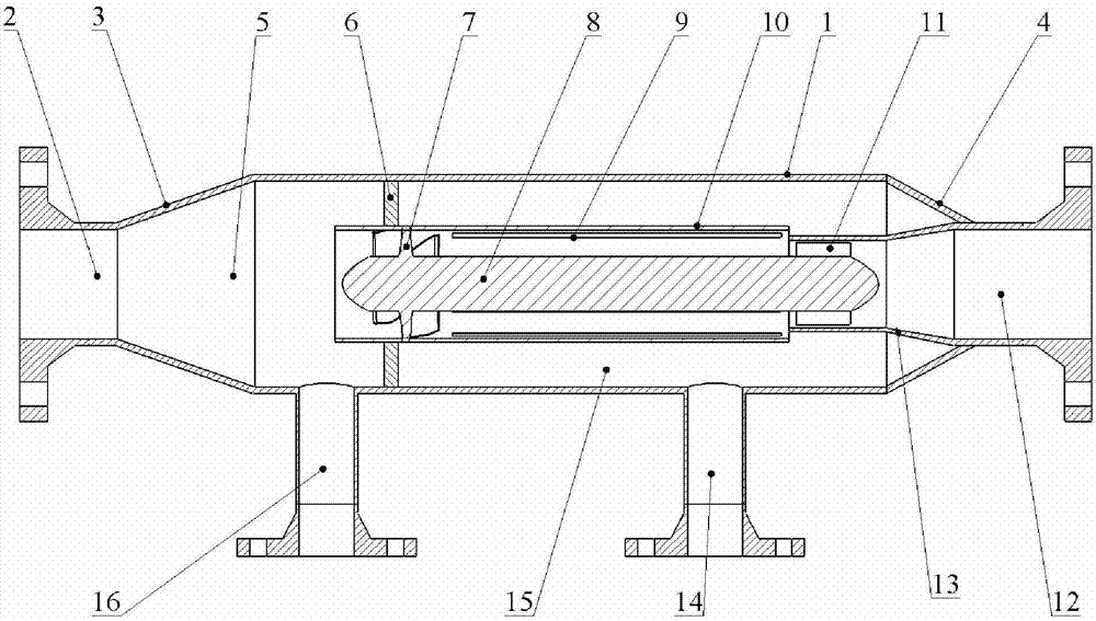
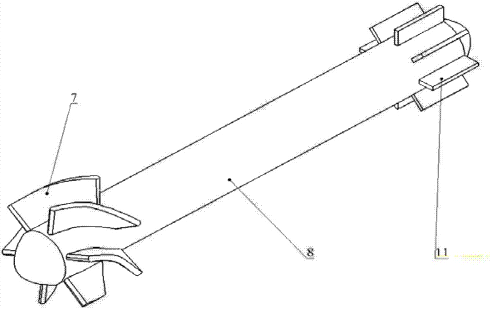
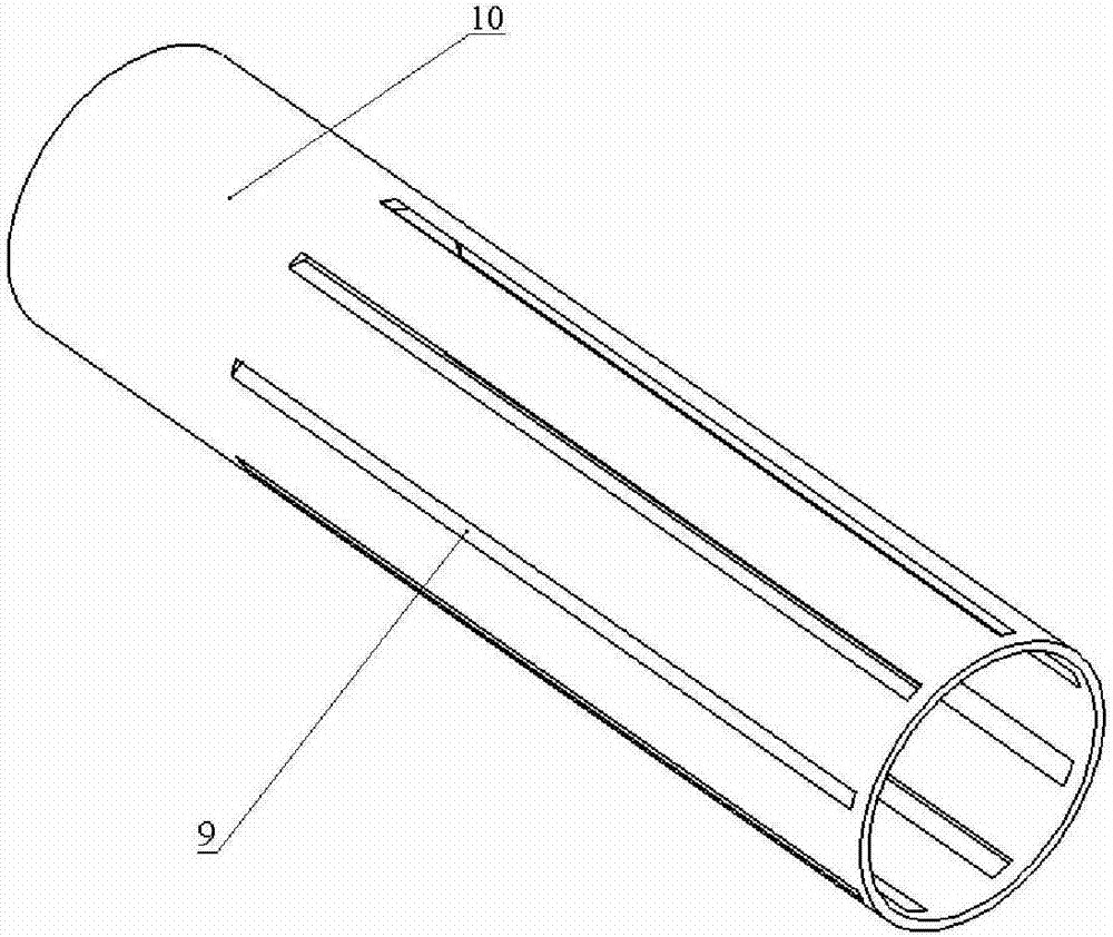
[0023] see figure 1 , a pipeline type natural gas condensate cyclone separator, the separator mainly includes a cylindrical body (1), an axial inlet (2), an inlet cone section (3), an outlet cone section (4), an axial Outlet (12), front liquid discharge pipe (16), rear liquid discharge pipe (14) constitute the outer shell, which is composed of annular plate (6), inner cylinder (10), guide body (8), inlet guide vane (7 ), supporting blades (11), and outlet gradual expansion section (13); among them, the annular plate (6) is located on the front half of the cylinder body (1), the outer ring is connected with the inner wall of the cylinder body (1), and the inner The ring is connected with the outer wall of the inner cylinder (10), and divides the interior of the separator into a pre-separation zone (5) and a m...


PUM


Abstract

The invention relates to a pipeline type natural gas condensed liquid rotating flow separator, which comprises a cylinder tube body, an axial inlet, an inlet cone section, an outlet cone section, an axial outlet, a front liquid discharging pipe, a back liquid discharging pipe, an annular plate, an inner tube, a flow guide body, an inlet guide blade and a support blade, wherein the inside of the separator is divided into a pre-separation region and a main separation region by the annular plate; the inner tube passes through the annular plate to extend in the separator and forms an annular cavity with the flow guide body; the inlet guide blade is formed by combining a smoothly transiting circular arc-shaped and linear blades; the outer edge and the inner edge of the inlet guide blade are respectively and fixedly connected with the inner tube and the flow guide body; a longitudinal seam is formed in the wall surface of the inner tube; the tail part and the outlet gradual expansion section form an annular opening; the inner edge of the support blade is connected with the tail end of the flow guide body; the outer edge of the support blade is connected with the linear pipe section of the outlet gradual expansion section. The pipeline type natural gas condensed liquid rotating flow separator has the advantages that the integral structure is compact; the two ends are provided with standard flanges; the pipeline connection with the pipeline and the dismounting from the pipeline are convenient; the separation efficiency is high; the pressure drop loss is small; a pre-separation region is installed; a good separation effect is achieved on the high-liquid-contact gas liquid incoming flow.

Description

technical field [0001] The invention relates to a pipeline type natural gas condensate cyclone separator, in particular to an online separator which combines gravity separation and centrifugal separation and is used for natural gas pipeline condensate separation. The invention belongs to the technical field of multiphase separation of oil and gas gathering and transportation systems. Background technique [0002] With the continuous development of gas fields, the content of free water and condensate in produced gas has gradually increased. Especially under the condition of undulating terrain, liquid accumulation is easy to form in the pipeline, which reduces the cross-sectional area of ​​pipeline transportation, increases the friction resistance of the gas production pipeline, and increases the back pressure of the wellhead, thus affecting the production capacity of the gas field. Therefore, the liquid components must be removed before the natural gas enters the gathering a...

Claims


Application Information

Patent Timeline
IPC IPC(8): B01D45/16C10L3/10
CPCB01D45/16C10L3/106
Inventor 罗小明高奇峰何利民吕宇玲杨东海
Owner CHINA UNIV OF PETROLEUM (EAST CHINA)
Learn More