A reaming clamping device

A clamping device and reaming technology, which is applied in the field of reaming processing, can solve the problems of reduced service life, non-straight hole wall generatrix, hole wall vibration lines, etc., and achieve long tool life, low hole wall roughness, and stable working conditions Effect

Active Publication Date: 2018-10-26
FOSHAN KEDA HYDRAULIC MACHINERY CO LTD
View PDF10 Cites 0 Cited by
  • Summary
  • Abstract
  • Description
  • Claims
  • Application Information

AI Technical Summary

Problems solved by technology

[0005] 2. The wide edge of the reamer 1a scrapes the hole wall, which causes the hole wall to vibrate, which in turn affects the service life of the reamer 1a and increases the processing cost;
[0006] 3. The operating accuracy of the machine tool spindle directly determines the accuracy of the inner hole 31a of the workpiece 3a, so the accuracy of the machine tool itself is extremely high, which increases the investment cost of the enterprise
[0008] 1. The reamer 1b is connected to the main shaft of the machine tool in a floating manner, and the axes still cannot completely overlap, and tail flicking will occur during floating connection processing;
[0009] 2. Tail flicking during processing will cause the generatrix of the hole wall of the workpiece 3a to be not straight and the hole diameters to be inconsistent;
[0010] 3. Tail flicking during processing will also cause the reamer 1b to work in an unstable state and reduce its service life
[0011] Therefore, the above two clamping devices have defects to varying degrees, and cannot guarantee the dimensional accuracy, shape accuracy and surface accuracy requirements of the plunger hole of the cylinder, and the service life of the reamer is relatively low.

Method used


Image

  • A reaming clamping device
  • A reaming clamping device
  • A reaming clamping device

Examples


Embodiment approach

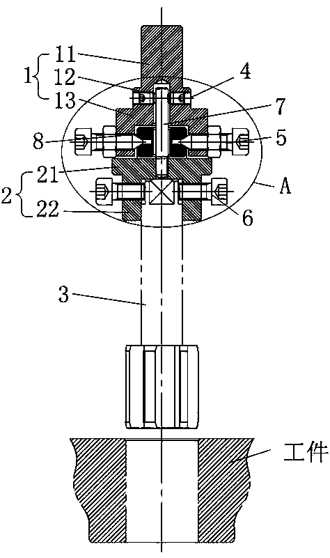
[0049] In the first embodiment, the first adjusting screw 4, the second adjusting screw 5 and the third adjusting screw 6 are all provided with three, and the three first adjusting screws 4 are evenly distributed along the circumferential direction of the fixing clamp handle 1, and the three The second adjusting screw 5 is evenly distributed along the circumferential direction of the clamp handle 1, and the three third adjusting screws 6 are evenly distributed along the circumferential direction of the tool mounting sleeve 2; when three are used, the adjustment can be realized more accurately, and the structure is simple.

[0050] The second embodiment, the first adjusting screw 4, the second adjusting screw 5 and the third adjusting screw 6 are all provided with four, and the four first adjusting screws 4 are evenly distributed along the circumferential direction of the fixing clamp handle 1, and the four A second adjusting screw 5 is evenly distributed along the circumferenti...


PUM


Abstract

The invention discloses a reaming and clamping device. The reaming and clamping device comprises a fixed clamping handle, a tool mounting sleeve and a reamer, wherein the fixed clamping handle, the tool mounting sleeve and the reamer are arranged in sequence from top to bottom. The reaming and clamping device further comprises first adjusting screws, second adjusting screws, third adjusting screws, a tool bit position adjusting rod and a universal moving block, wherein the upper portion and the lower portion of the tool bit position adjusting rod are inserted into the fixed clamping handle and the tool mounting sleeve correspondingly, and the universal moving block is arranged outside the tool bit position adjusting rod in a sleeving manner. A mounting chamber with a downward opening is formed in the fixed clamping handle, and the universal moving block is mounted in the mounting chamber. The first adjusting screws lock the fixed clamping handle to the upper end of the tool bit position adjusting rod in multiple radial directions at the same axial height of the fixed clamping handle; the second adjusting screws lock the universal moving block to the tool bit position adjusting rod in multiple radial directions at the same axial height of the fixed clamping handle; and the third adjusting screws lock the tool mounting sleeve to a handle of the reamer in multiple radial directions at the same axial height of the tool mounting sleeve. The first adjusting screws are located above the second adjusting screws. The clamping device is stable in structure in the working process, and machined workpieces are high in precision.

Description

technical field [0001] The invention relates to the technical field of reaming processing, in particular to a clamping device for reaming processing of precision inner holes. Background technique [0002] When developing a hydraulic plunger pump, there are extremely high requirements for the dimensional accuracy, shape accuracy and surface accuracy of the plunger hole of the cylinder body. One of the key factors, the prior art generally adopts the following two clamping devices to ream the plunger hole. [0003] See attached figure 1 As shown, the first clamping device adopts a rigid clamping method, and the reamer 1a is rigidly connected to the machine tool spindle. Due to the manufacturing error of the reamer 1a and the accuracy error of the machine tool itself, the reamer centerline 11a and the machine tool spindle centerline 2a cannot be completely overlapped, and the processing will bring the following effects: [0004] 1. After the workpiece 3a hole is processed, th...

Claims


Application Information

Patent Timeline
Patent Type & Authority Patents(China)
IPC IPC(8): B23D75/00B23Q3/12
CPCB23D75/00B23Q3/12
Inventor 吴德福何浩波
Owner FOSHAN KEDA HYDRAULIC MACHINERY CO LTD
Why Eureka
Try Eureka