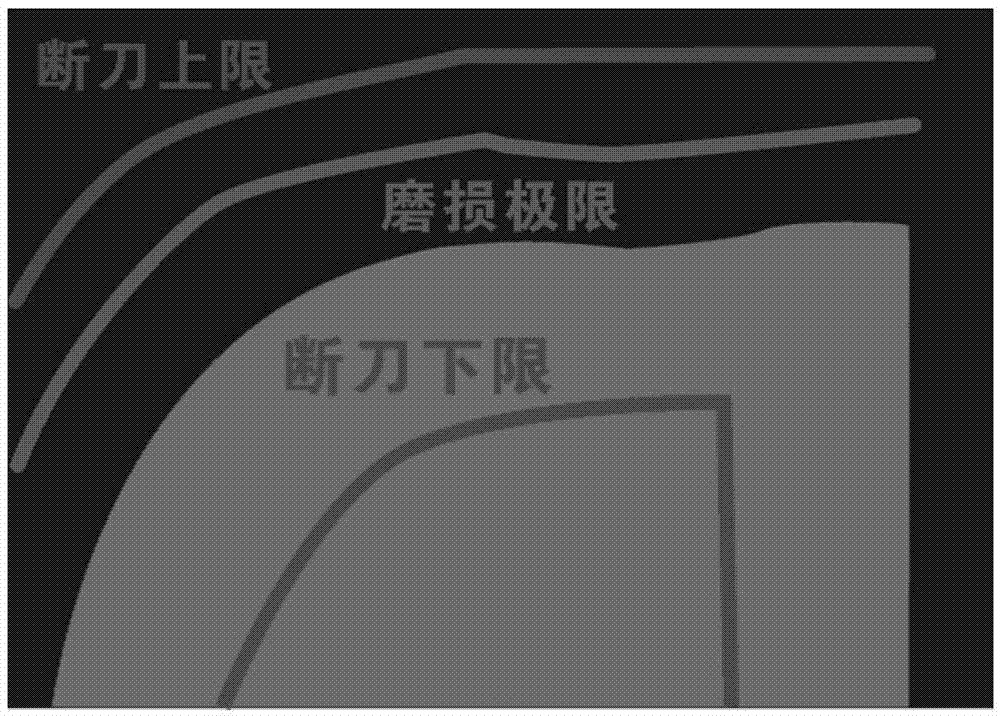
Cutter monitoring method and system based on image analysis

An image analysis and cutting tool technology, which is applied in the direction of manufacturing tools, metal processing machinery parts, measuring/indicating equipment, etc., can solve the problems of tool observation, low efficiency, and complicated monitoring methods, and achieve the effect of simple monitoring and fast observation

Inactive Publication Date: 2017-06-20
周萍萍 +1
View PDF6 Cites 15 Cited by
  • Summary
  • Abstract
  • Description
  • Claims
  • Application Information

AI Technical Summary

Problems solved by technology

[0004] However, in the above-mentioned methods, all the images collected are tool images, and the user cannot intuitively and quickly observe the state of the tool. The monitoring method is more complicated and less efficient.

Method used


Image

  • Cutter monitoring method and system based on image analysis
  • Cutter monitoring method and system based on image analysis
  • Cutter monitoring method and system based on image analysis

Examples


Embodiment Construction

[0052] The present invention will be described in further detail below in conjunction with the accompanying drawings and specific embodiments. It should be understood that the specific embodiments described here are only used to explain the present invention, not to limit the present invention.

[0053] It should be noted that the "connection" mentioned in this application and the words used to express "connection", such as "connected", "connected", etc., can refer to the direct connection between a certain component and another component, It can also mean that a certain component is connected to another component through other components.

[0054] The embodiment of the present invention discloses a tool monitoring method based on image analysis, the method includes three monitoring modes,

[0055] Monitoring mode one:

[0056] Including learning status and monitoring status,

[0057]The learning state includes the following steps:

[0058] Step 1: Monitoring tool-related ...


PUM


Abstract

The invention discloses a cutter monitoring method and system based on image analysis. The cutter monitoring method based on image analysis comprises the steps that a relevant feature signal of a cutter is monitored through a sensor; after being amplified by an amplifier, the amplified relevant feature signal of the cutter is sent to a main board; the main board stores and analyzes the relevant feature signal of the cutter, and then the main board sends the analyzed data to a display device; and the display device displays the analyzed data in an image form. According to the cutter monitoring method and system based on image analysis, the signal of one of the motor current, the motor power, the motor torque or the value or percentage of the pressure and a acoustic wave is collected by the sensor, the monitoring result is displayed in the image form, a user can visually and rapidly observe the monitoring result, and monitoring is easier and more efficient.

Description

technical field [0001] The invention belongs to the technical field of tool wear monitoring of numerical control machine tools, and in particular relates to a tool monitoring method and system based on image analysis. Background technique [0002] Over the years, scholars at home and abroad have done a lot of work in the online monitoring of tool wear, and have achieved remarkable results in the fields of monitoring methods, monitoring parameter selection, and signal processing and identification. Some methods have been used in production. [0003] The traditional tool wear state monitoring method is based on the relevant characteristics of the tool volume loss, and directly obtains the tool wear value through contact measurement or CCD imaging. For example, see the Chinese patent application number: CN200910031737.9, and the title of the invention is: CNC milling tool wear measurement method based on shape replication, which copies the shape of the tool on the copy material...

Claims


Application Information

Patent Timeline
Patent Type & Authority Applications(China)
IPC IPC(8): B23Q17/09
CPCB23Q17/0961
Inventor 周萍萍魏明
Owner 周萍萍
Why Eureka
Try Eureka