
Installation method of pipeline bridge crossing canyon

An installation method and pipeline bridge technology, applied in bridges, bridge applications, bridge construction, etc., can solve problems such as difficult quality control, long construction period, and poor safety, and achieve the effects of easy quality control, shortened construction period, and reduced construction cost

Active Publication Date: 2017-06-20
中石化江苏油建工程有限公司
View PDF6 Cites 1 Cited by
  • Summary
  • Abstract
  • Description
  • Claims
  • Application Information

AI Technical Summary

Problems solved by technology

Faced with the construction task of pipeline bridges that need to cross both sides of the canyon, if the traditional technology is used for construction, firstly, the construction period is too long, which will affect the overall construction progress of the oil and gas pipeline; secondly, the cost of erecting full house scaffolding is too high; High-altitude operations, poor safety, difficult quality control, and the most critical thing is that it is difficult to find large-scale lifting equipment that meets the requirements on the construction site

Method used


Image

  • Installation method of pipeline bridge crossing canyon
  • Installation method of pipeline bridge crossing canyon
  • Installation method of pipeline bridge crossing canyon

Examples


Embodiment Construction

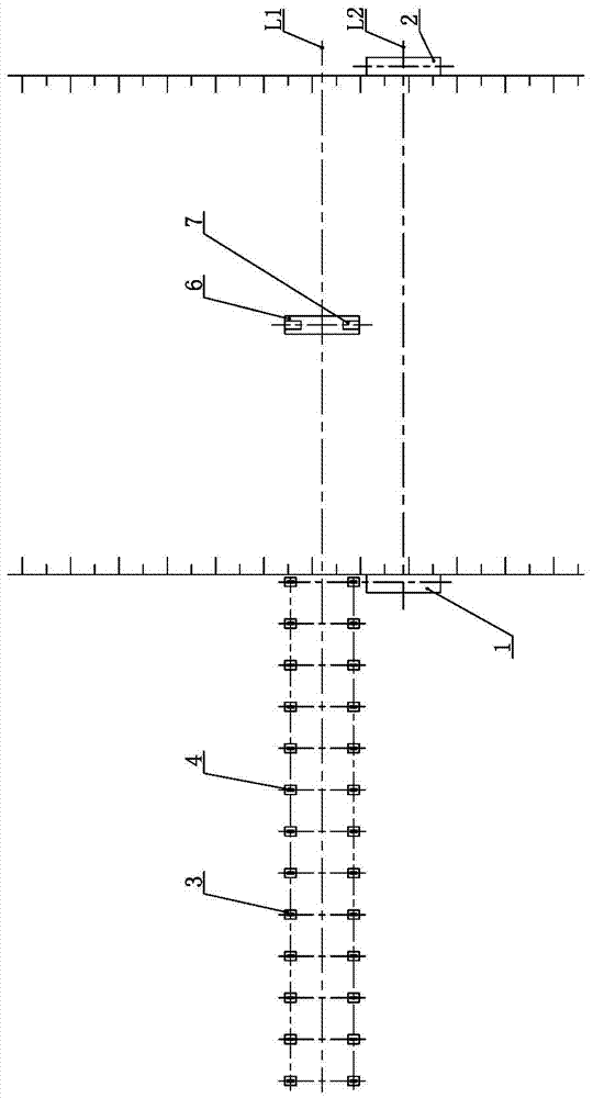
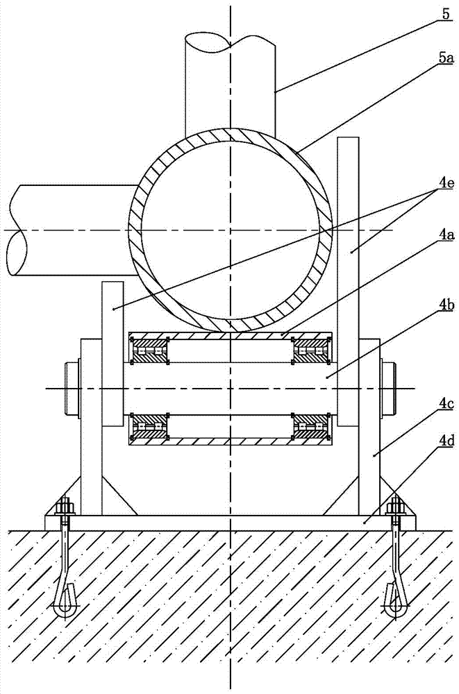
[0028] Such as Figure 1 to Figure 9 As shown, the installation method of the pipeline bridge crossing the canyon of the present invention includes the following steps in sequence: (1) Measure and set the line, determine the crossing line L1 on the canyon section, and determine the positions of the left pier 1 and the right pier 2 on the left and right banks of the canyon , The left pier 1 and right pier 2 are located on the crossing line L1; (2) the left pier 1 and the right pier 2 are poured on the left and right banks of the canyon, and the inherent pipeline bridge connection embedded parts are anchored on the top of the left pier 1 and right pier 2 respectively; (3) A transmission line L2 parallel to the crossover line L1 is set on the front or back side of the crossover line L1, and the center distance between the transmission line L2 and the crossover line L1 is 1.2 to 1.5 times the width of the pipeline bridge 5; ⑷ in the canyon The pipeline bridge 5 is made on the left b...


PUM


Abstract

The invention relates to an installation method of a pipeline bridge crossing a canyon. The method comprises the steps of 1, surveying and setting-out, wherein a crossing line is determined on a canyon cross section, positions of left and right bridge piers at left and right banks of the canyon are determined, and the left and right bridge piers are located at the crossing line; 2, pouring the left and right bridge piers at the left and right banks of the canyon, wherein pipeline bridge connecting built-in fittings are anchored at the tops of the left and right bridge piers respectively; 3, determining a sending line parallel to the crossing line at the front side or rear side of the crossing line, wherein the center distance between the sending line and the crossing line is 1.2-1.5 folds of the width of the pipeline bridge; 4, manufacturing the pipeline bridge at the left bank of the canyon and mounting a sending device in the middle of the canyon bottom of the canyon, wherein both the pipeline bridge and the sending device are located at the sending line; 5, making the pipeline bridge cross the canyon along the sending line; 6, transferring the pipeline bridge horizontally with a crane to the crossing line and fixing the pipeline bridge on the left and right bridge piers. According to the installation method of the pipeline bridge crossing the canyon, pipeline bridge crossing can be completed in canyon areas where there is no heavy cranes, and the method is short in construction period, low in manufacturing cost and high in safety.

Description

Technical field [0001] The invention relates to a pipeline bridge, in particular to an installation method for a pipeline bridge crossing a canyon, and belongs to the technical field of pipeline bridge construction. Background technique [0002] To cross the canyon, the oil and natural gas pipeline must first install a pipeline bridge across the canyon, and then lay the pipeline along the pipeline bridge. The traditional construction method of the pipeline bridge across the canyon requires scaffolding to be erected along the cross section of the canyon first, and the scaffolding needs to be erected from one side of the canyon to the opposite bank, commonly known as erecting red scaffolding. Then, the pipeline bridge was manufactured and installed on-site on the full house red scaffolding. The welding team worked on all personnel at high altitudes above the canyon, and was assisted by cranes with large lifting capacity for construction. This conventional construction method requir...

Claims


Application Information

Patent Timeline
IPC IPC(8): E01D21/00E01D18/00
CPCE01D18/00E01D21/00
Inventor 戚国顺黄国王浩姜偲王振家
Owner 中石化江苏油建工程有限公司
Learn More