
Reciprocating impact part of multistage protection sealing telescopic sleeve

A telescopic shaft sleeve and impact part technology, applied in cutting machinery, earth-moving drilling, slitting machinery, etc., can solve problems such as increased power consumption, leakage of lubricating and cooling medium, poor sealing effect, etc.

Active Publication Date: 2017-06-20
刘素华
View PDF6 Cites 3 Cited by
  • Summary
  • Abstract
  • Description
  • Claims
  • Application Information

AI Technical Summary

Problems solved by technology

[0002] Because the blanking method of the reciprocating impact mining machine is reciprocating knocking and blanking, the utilization rate of kinetic energy is high and the dust is less, so the reciprocating impact blanking method is very popular. However, due to the single Due to the reaction force of reciprocating impact and the frequent impact of external forces such as materials on the seal, damage to the sealing telescopic surface of the guide impact part and damage to the box seal, resulting in leakage of the lubricating and cooling medium in the reciprocating impact box, dust , muddy water, materials, etc. enter the reciprocating impact box, resulting in damage to the power system components in the reciprocating impact box, unable to work continuously for a long time, repair and replace the bearings, crankshaft, connecting rod, guide The impact parts, guide parts, etc. require a lot of labor and time, and it is even difficult to complete the maintenance work. In order to protect the guide impact parts, box seals, etc., a protective plate was added around the square reciprocating impact box, and the protective plate was held in the reciprocating Outside the impact box, because the protective plate is higher and wider than the reciprocating impact box, the reciprocating movement of the protective plate with the guiding impact piece increases power consumption, increases the overall weight of the reciprocating impact head, and greatly increases the impact between the protective plate and the reciprocating impact. It is difficult to seal between the impact boxes, the overall cost of the protective structure is high, and it is difficult to manufacture, and because the two guiding impact parts are arranged on the same crankshaft, there must be a gap between the front and rear staggered protective plates, and materials, dust, Muddy water enters between the protective plate and the reciprocating impact box from multiple gaps in the protective plate. After a large amount of accumulation for a long time, the material hardens and forms a cushion between the protective plate and the reciprocating impact box. The thickening of the cushion layer continues to block the reciprocating impact. The head retracts backwards, causing the reciprocating punch to fall off, thus causing the overall structure of the reciprocating impact excavator to be reasonable, but the supporting detailed structure and components cannot meet the requirements for long-term effective work of the reciprocating impact excavator, and even bring a huge shutdown to the user loss, the reciprocating impact mining machine has not been able to make energy-saving and environmental-friendly contributions to mining mining. In order to solve the above problems, the present invention proposes a reciprocating impact part of a multi-stage protective seal telescopic shaft sleeve

Method used


Image

  • Reciprocating impact part of multistage protection sealing telescopic sleeve
  • Reciprocating impact part of multistage protection sealing telescopic sleeve
  • Reciprocating impact part of multistage protection sealing telescopic sleeve

Examples


Embodiment 1

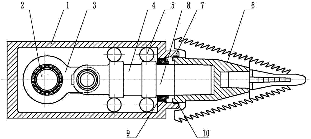
[0044] Such as figure 1 As shown, a reciprocating impact part of a multi-stage protective seal telescopic sleeve includes a multi-stage protective guide shaft casing 1, a crankshaft 2, a connecting rod 3, a guide impact member 4, a guide member 5 and a main reciprocating tooth 6, etc., and the multi-stage The guide shaft housing 1 supports the guide piece 5, etc. The guide piece 5 supports the guide impact piece 4 and guides the guide impact piece 4, the crankshaft 2 is connected with the connecting rod 3, the crankshaft 2 drives the connecting rod 3, and the connecting rod 3 drives the guide impact piece 4 Reciprocating impact, crankshaft 2, connecting rod 3, guide impact piece 4, guide piece 5, etc. are arranged in the multi-stage protective guide shaft box 1, one end of the guide impact piece 4 protrudes outside the multi-stage guide shaft box 1, and the guide impact The multi-stage protective guide shaft casing 1 at the extension end of the part 4 is provided with a multi-...

Embodiment 2

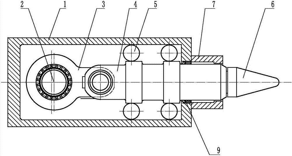
[0047] Such as figure 2 As shown, a reciprocating impact part of a multi-stage protective seal telescopic sleeve includes a multi-stage protective guide shaft casing 1, a crankshaft 2, a connecting rod 3, a guide impact member 4, a guide member 5 and a main reciprocating tooth 6, etc., and the multi-stage The guide shaft housing 1 supports the guide piece 5, etc. The guide piece 5 supports the guide impact piece 4 and guides the guide impact piece 4, the crankshaft 2 is connected with the connecting rod 3, the crankshaft 2 drives the connecting rod 3, and the connecting rod 3 drives the guide impact piece 4 Reciprocating impact, crankshaft 2, connecting rod 3, guide impact piece 4, guide piece 5, etc. are arranged in the multi-stage protective guide shaft box 1, one end of the guide impact piece 4 protrudes outside the multi-stage guide shaft box 1, and the guide impact The multi-stage protective guide shaft casing 1 at the extension end of the part 4 is provided with a multi...

Embodiment 3

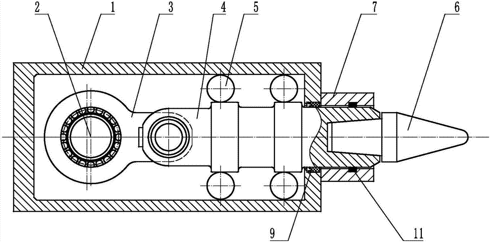
[0050] Such as image 3 As shown, a reciprocating impact part of a multi-stage protective seal telescopic sleeve includes a multi-stage protective guide shaft casing 1, a crankshaft 2, a connecting rod 3, a guide impact member 4, a guide member 5 and a main reciprocating tooth 6, etc., and the multi-stage The guide shaft casing 1 supports the guide piece 5, the guide piece 5 supports the guide impact piece 4 and guides the guide impact piece 4, the crankshaft 2 is connected with the connecting rod 3, the crankshaft 2 drives the connecting rod 3, and the connecting rod 3 drives the guide impact piece 4 to reciprocate Impact, crankshaft 2, connecting rod 3, guide impact piece 4, guide piece 5, etc. are arranged in the multi-stage protection guide shaft box body 1, one end of the guide impact piece 4 protrudes outside the multi-stage protection guide shaft box body 1, and the guide impact piece 4 The multi-stage protective guide shaft casing 1 at the protruding end is provided wi...


PUM


Abstract

The invention relates to the field of mining machineries, in particular to a reciprocating impact part of a multistage protection sealing telescopic sleeve. The reciprocating impact part structurally comprises a multistage protection guide shaft box body, a crankshaft, a connecting rod, a guide impact piece, guide pieces and a main reciprocating tooth. The multistage protection guide shaft box body supports the guide pieces; the guide pieces support the guide impact piece to guide the guide impact piece; the crankshaft is connected with the connecting rod; and the crankshaft drives the connecting rod driving the guide impact piece to impact in a reciprocating mode. One end or the two ends of the guide impact piece stretches / stretch out of the multistage protection guide shaft box body; and the multistage protection sealing telescopic sleeve is arranged in the position, at the stretching end of the guide impact piece, of the multistage protection guide shaft box body. The guide impact piece comprises a guide rod sealing section. The shape of the cross section of the inner diameter of the multistage protection sealing telescopic sleeve is matched with the shape of the cross section of the outer diameter of the guide rod sealing section. The guide rod sealing box body section and a box body sealing piece are matched to prevent dust, muddy water, material and the like from entering the box body. According to the structure, maintenance in site is reduced, the maintenance cost is saved, the service life of a reciprocating mining machine is greatly prolonged, and the practical efficiency of the reciprocating mining machine is greatly improved.

Description

technical field [0001] The invention relates to the field of excavation machinery, in particular to a reciprocating impact part of a multi-stage protective seal telescopic shaft sleeve. Background technique [0002] Because the blanking method of the reciprocating impact mining machine is reciprocating knocking and blanking, the utilization rate of kinetic energy is high and the dust is less, so the reciprocating impact blanking method is very popular. However, due to the single Due to the reaction force of reciprocating impact and the frequent impact of external forces such as materials on the seal, damage to the sealing telescopic surface of the guide impact part and damage to the box seal, resulting in leakage of the lubricating and cooling medium in the reciprocating impact box, dust , muddy water, materials, etc. enter the reciprocating impact box, resulting in damage to the power system components in the reciprocating impact box, unable to work continuously for a long ...

Claims


Application Information

Patent Timeline
Patent Type & Authority Applications(China)
IPC IPC(8): E21C25/04E21C35/08E21C35/00
CPCE21C25/04E21C35/00E21C35/08
Inventor 刘素华
Owner 刘素华
Learn More