Multi-working-condition multi-stage turbine

A multi-working condition, turbine technology, applied in the directions of hydroelectric power generation, engine components, machines/engines, etc., can solve the problems of increasing the working stability of the machine, unable to improve the efficiency of changing working conditions, etc., to improve efficiency and stability, reduce Vibration, reducing the effect of cavitation damage

Inactive Publication Date: 2017-06-20
JIANGSU UNIV ZHENJIANG RES INST OF FLUID ENG EQUIP TECH
View PDF8 Cites 5 Cited by
  • Summary
  • Abstract
  • Description
  • Claims
  • Application Information

AI Technical Summary

Problems solved by technology

[0006] However, the above-mentioned patents can only increase the stability of the machine when the working conditions change, but cannot improve the efficiency of the changing working conditions.

Method used


Image

  • Multi-working-condition multi-stage turbine
  • Multi-working-condition multi-stage turbine
  • Multi-working-condition multi-stage turbine

Examples


Embodiment Construction

[0040] The present invention will be further described below with reference to the accompanying drawings and specific embodiments.

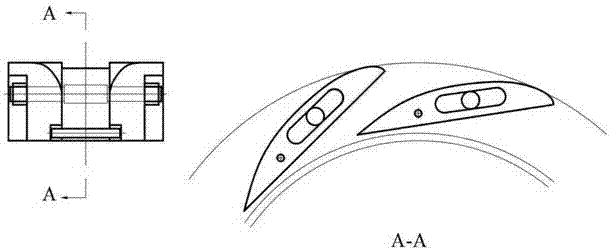
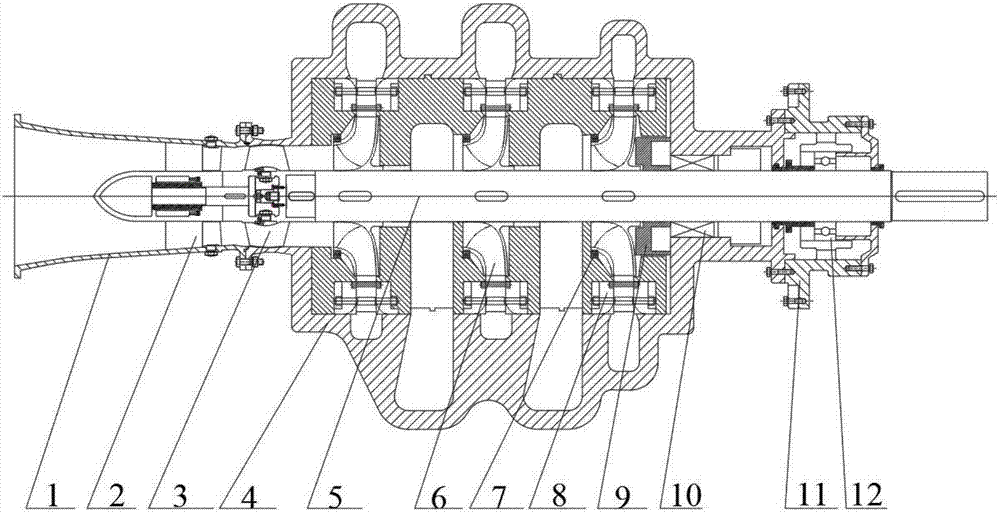
[0041] A multi-working-condition multi-stage turbine, which includes draft tube 1, segmented guide vane 2, axial flow impeller 3, casing 4, main shaft 5, centrifugal impeller 6, mouth ring 7, movable guide vane 8, Balance plate 9, mechanical seal 10, bearing seat 11, deep groove ball bearing 12;

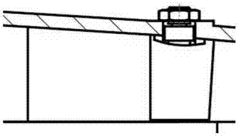
[0042] The housing 4 is divided into upper and lower parts along the horizontal plane of the main shaft 5, and the upper and lower parts of the housing 4 are connected by bolts;

[0043] The draft tube 1 is connected to one side of the casing 4 through bolts;

[0044] The centrifugal impeller 6 is fixed to the main shaft 5 through a shaft sleeve and a keyway; the first stages of the turbine are several single-suction centrifugal impellers 6;

[0045] The last stage centrifugal impeller 6 is provided with an axial flow impeller 3, and the axial flow im...


PUM


Abstract

The invention provides a multi-working-condition multi-stage turbine. The multi-working-condition multi-stage turbine comprises a draft tube, a sectional type guide vane, an axial-flow impeller, a shell, a main shaft, centrifugal impellers, impeller rings, movable guide vanes, a balance disc, a mechanical seal, a bearing pedestal and a deep groove ball bearing. The multi-working-condition multi-stage turbine aims to improve the efficiency and the stability of the turbine under the variable working conditions. The multi-stage centrifugal impellers are suitable for recycling the energy with high energy head fluid. The movable guide vanes can play a role in flow adjustment, and can also be used for adjusting the inflow angle and reducing the inflow impact loss when the condition deviates from the designed working condition. Similarly, the sectional type guide vane is designed for adapting to different working conditions, and can effectively eliminate the circulation of water flow in the draft tube, and therefore the cavitation damage to the draft tube is greatly reduced, and the vibration of the draft tube is weakened.

Description

technical field [0001] The invention relates to a turbine device, in particular to a multi-working-condition multi-stage turbine device. Background technique [0002] A turbine is a machine that converts the energy contained in a fluid working medium into mechanical energy. There are a large number of high-pressure liquids in petrochemical, petroleum processing, chemical fertilizer, seawater desalination, iron and steel metallurgy and other industries, and the energy of these high-pressure liquids is mostly wasted at present. In foreign countries, some developed countries currently use the energy of these high-pressure liquids with special hydraulic energy recovery turbines, but in my country and some developing countries, most of the energy is wasted, and it has also been used in the fertilizer industry in China in recent years. A device that reverses the pump to recover, but due to the lack of design theory, the energy recovery efficiency is generally low, which leads to t...

Claims


Application Information

Patent Timeline
Patent Type & Authority Applications(China)
IPC IPC(8): F03B3/02F03B3/18F03B11/00F03B3/16F03B3/12F03B11/04
CPCF03B3/02F03B3/125F03B3/16F03B3/183F03B11/006F03B11/04Y02E10/20
Inventor 付强陈铭朱荣生王秀礼张本营刘刚李梦圆张国玉
Owner JIANGSU UNIV ZHENJIANG RES INST OF FLUID ENG EQUIP TECH
Why Eureka
Try Eureka