Tee-joint switching device for boiler denitration

A three-way and denitration technology, applied in the chemical industry, can solve the problems of boiler negative pressure fluctuation, increase the frame height, and stop the furnace, and achieve the effect of reducing the construction workload, avoiding erosion and wear, and saving investment costs.

Active Publication Date: 2017-06-20
冯力燕
View PDF4 Cites 0 Cited by
  • Summary
  • Abstract
  • Description
  • Claims
  • Application Information

AI Technical Summary

Problems solved by technology

[0002] Since boilers generally use diesel oil and heavy oil to ignite, after the selective catalytic reduction (SCR) denitrification process is adopted, a large amount of incompletely burned oil fume will adhere to the surface of the SCR denitrification catalyst, resulting in a decrease in the surface activity of the catalyst. Pollution is an irreversible process and cannot be cleaned up. In severe cases, the catalyst may fail in a large area once the furnace is turned on.
After the catalyst is polluted, the nitrogen oxides exceed the standard, seriously polluting the environment, and even forced to stop the furnace to replace the catalyst
When the boiler bursts and leaks, a large amount of water vapor will enter the denitrification reactor, and the dust in the flue gas will form adhesion deposits in the catalyst, which will affect the catalytic reaction efficiency and reduce or even fail or block, causing serious environmental impact and even forced to shut down the furnace deal with
[0003] In order to avoid the above accidents, the existing boiler generally adopts a bypass design when adding a denitrification device. It is necessary to add a damper and an expansion joint to the inlet and outlet flue of the denitrification reactor, and also add a damper and an expansion joint to the shortcut, which has the advantages of The following disadvantages: large investment; there must be enough space, so the height of the frame needs to be increased, which increases the difficulty of investment and construction; the operation adjustment is very cumbersome, and if the coordination is not in place, the negative pressure of the boiler will fluctuate or even stop the fire.

Method used


Image

  • Tee-joint switching device for boiler denitration
  • Tee-joint switching device for boiler denitration
  • Tee-joint switching device for boiler denitration

Examples


Embodiment Construction

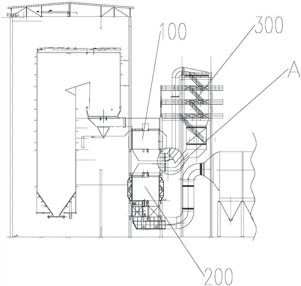
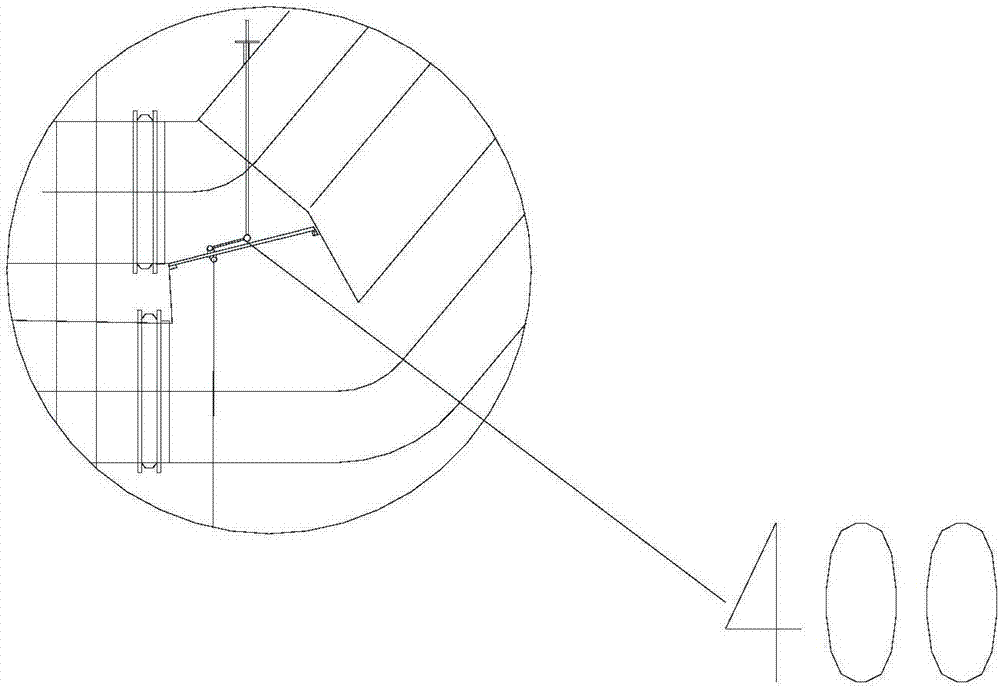
[0028] figure 1 It is a schematic diagram of a boiler using a three-way switching device in an embodiment of the present invention. figure 2 yes figure 1 Enlarged view of A. combine figure 1 and figure 2 It can be seen that the three-way switching device 400 for boiler denitration of the present invention is located between the denitration reactor 300 , the low-temperature economizer or air preheater 200 , and the high-temperature economizer or air preheater 100 .

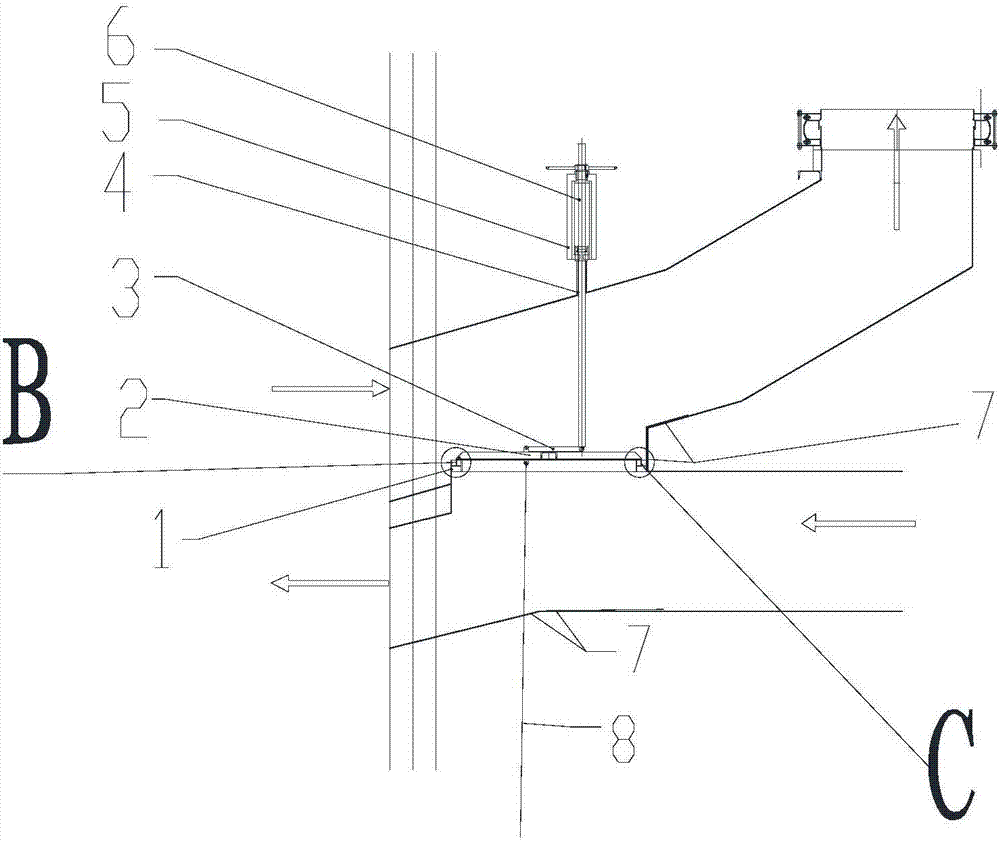
[0029] image 3 It is a structural schematic diagram of the three-way switching device when the sealing baffle is closed in another embodiment of the present invention. Such as image 3 As shown, the boiler denitrification tee switching device 400 of this embodiment includes a frame 1 and a sealing baffle 2 .

[0030] The frame 1 is located at the connection between the inlet and outlet of the flue of the denitration reactor, the flue of the low-temperature economizer or the air preheater, and the flue of ...


PUM


Abstract

The invention provides a tee-joint switching device for boiler denitration. The tee-joint switching device comprises a frame and a sealing baffle. The frame is located among the connection position of an inlet and an outlet of a flue of a denitration reactor, a flue of a low-temperature coal economizer or air pre-heater and a flue of a high-temperature coal economizer or air pre-heater. The sealing baffle is arranged on the frame, located at one end of the connection position of the inlet and the outlet of the denitration reactor and hinged to the frame. The sealing baffle can move vertically with the connection position of the inlet and the outlet of the flue of the denitration reactor as the axis, and thus the tee-joint switching device can be opened and closed.

Description

technical field [0001] The invention relates to the field of chemical industry, in particular to a three-way switching device for boiler denitrification. Background technique [0002] Since boilers generally use diesel oil and heavy oil to ignite, after the selective catalytic reduction (SCR) denitrification process is adopted, a large amount of incompletely burned oil fume will adhere to the surface of the SCR denitrification catalyst, resulting in a decrease in the surface activity of the catalyst. Pollution is an irreversible process and cannot be cleaned up. In severe cases, the catalyst may fail in a large area once the furnace is turned on. After the catalyst is polluted, the nitrogen oxides exceed the standard, seriously polluting the environment, and even forced to stop the furnace to replace the catalyst. When the boiler bursts and leaks, a large amount of water vapor will enter the denitrification reactor, and the dust in the flue gas will form adhesion deposits i...

Claims


Application Information

Patent Timeline
Patent Type & Authority Applications(China)
IPC IPC(8): F23J15/00B01D53/86B01D53/56
CPCB01D53/8631F23J15/006F23J2215/10Y02E20/34
Inventor 冯力燕
Owner 冯力燕
Why Eureka
Try Eureka