Ammonia escape in situ laser detection device

A technology of laser detection and ammonia escape, which is applied in measurement devices, material analysis by optical means, instruments, etc., can solve the problems of insufficient measurement accuracy, increased maintenance, and inaccurate laser beams, so as to solve the problem of flue gas stagnation. , Improve fluidity, increase the effect of optical path

Inactive Publication Date: 2017-06-20
GUANGZHOU SENSER ELECTROMECHANICAL EQUIP CO LTD
View PDF8 Cites 0 Cited by
  • Summary
  • Abstract
  • Description
  • Claims
  • Application Information

AI Technical Summary

Problems solved by technology

[0006] 2. In order to solve the problem that the transmittance is insufficient and cannot be measured, many in-situ analyzers adopt an oblique angle installation method in the flue gas flow channel, but due to reasons such as weak angle fluidity and flue gas flow, the measurement effect poor
[0007] 3. The dust content in the flue gas is too high. In order to solve the problem of transmittance, it is installed at an oblique angle. There is also a problem that the laser light path of the instrument is short and the measurement accuracy is not enough. The measurement data is prone to fluctuations.
[0008] 4. The in-situ instrument is divided into a transmitting end and a reflecting end. Due to vibration, thermal expansion or settlement of the flue gas channel, the emitting end and the reflecting end are not on the same straight line, and the laser alignment is inaccurate, and the instrument has no reading or data. Jumping and other conditions affect the normal use of the instrument
[0009] 5. The flue gas channel sometimes contains a lot of dust, and the surface of the transmitter and reflector probes of the in-situ instrument is easy to accumulate dust, which will cause the lens of the transmitter and receiver to be blocked, resulting in increased maintenance. The maintenance cycle needs 1-2 weeks
[0010] Due to the various reasons listed above, the in-situ detection device has gradually reduced its domestic market share and cannot play its due role.

Method used


Image

  • Ammonia escape in situ laser detection device
  • Ammonia escape in situ laser detection device
  • Ammonia escape in situ laser detection device

Examples


Embodiment Construction

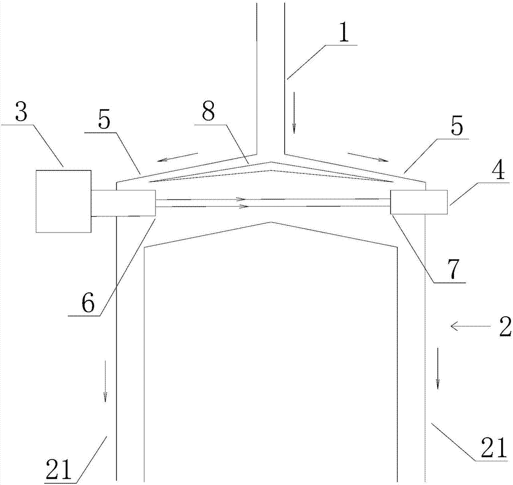
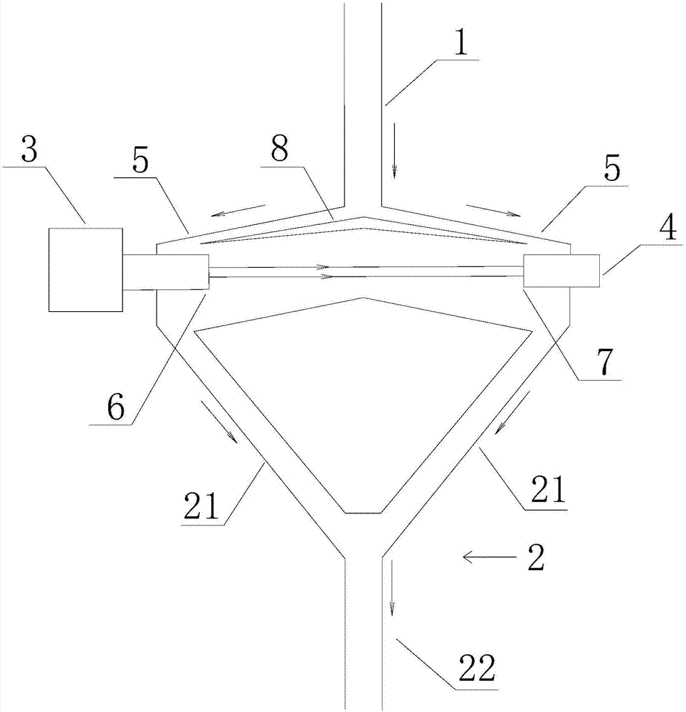
[0029] The present invention will be described in detail below in conjunction with accompanying drawing, as figure 1 As shown: the ammonia escape in-situ laser detection device of this embodiment includes an air inlet pipe 1, an air outlet pipe 2, a laser emitting unit 3 and a laser receiving unit 4, and the air outlet of the air inlet pipe is connected with two left and right branches Pipeline 5, the air inlet pipe is in an inverted Y shape after being communicated with two branch pipes; the air outlet of the two branch pipes is communicated with the air outlet pipe; the air outlet pipe includes two air outlet sub-pipes 21, the two The gas outlet sub-pipes are respectively connected to the two branch pipes; the laser emitting unit and the laser receiving unit are respectively arranged at the ends of the left and right branch pipes, and the emitting area 6 of the laser emitting unit is in the same direction as the receiving area 7 of the laser receiving unit. To relative.

[...


PUM


Abstract

The invention discloses an ammonia escape in situ laser detection device, comprising an air inlet pipeline, an air outlet pipeline, a laser emitting unit and a laser receiving unit, wherein an air outlet of the air inlet pipeline is provided with left and right branch pipelines, and the air inlet pipeline is communicated with the two branch pipelines to be in a reversed Y shape; air outlets of the two branch pipelines are communicated with an air inlet of the air outlet pipeline, and the laser emitting unit and the laser receiving unit are respectively arranged at the end parts of the left and right branch pipelines; an emitting region of the laser emitting unit is positively opposed to a receiving region of the laser receiving unit. The air inlet pipeline is communicated with the two branch pipelines to be in a reversed Y shape, and the structure is relatively simple, so that the problem of flue gas stagnation due to a too large flow cell of large-scale detection equipment is solved, the flowability of a flue gas is improved, and the impact of a large amount of dust in the flue gas on the detection effect of ammonia escape is alleviated. The structure is also favorable for increasing the optical path, and further improving the accuracy of ammonia escape detection.

Description

technical field [0001] The invention relates to a flue gas detection device, in particular to an ammonia escape laser absorption spectrum in-situ detection device. Background technique [0002] As environmental protection issues become increasingly prominent, the state's supervision of some high-energy-consuming enterprises has also been strengthened accordingly. In fields that rely on large-scale combustion of fossil fuels, such as coal-fired power plants, after desulfurization transformation was carried out in previous years, the call for denitrification transformation has increased accordingly. At present, most power plants use the ammonia injection denitrification method, that is, pre-combustion or post-combustion NO X Control technology denitrification device, post-combustion NO X The control technology can be a selective catalytic reduction method or a selective non-catalytic reduction method, but both of them inject ammonia into the reactor to react with nitrogen ox...

Claims


Application Information

Patent Timeline
Patent Type & Authority Applications(China)
IPC IPC(8): G01N21/01
CPCG01N21/01
Inventor 庞灿
Owner GUANGZHOU SENSER ELECTROMECHANICAL EQUIP CO LTD
Why Eureka
Try Eureka