Temperature control method and temperature control system

A temperature control method and technology of a temperature control system, which are applied in the direction of temperature control, control/regulation system, non-electric variable control, etc., can solve the problems of high operating frequency of power switch tubes, increased volume and weight, large switching loss, etc. The effect of electrical stress, continuous current and saving volume and weight

Active Publication Date: 2017-06-20
11TH RES INST OF CHINA ELECTRONICS TECH GROUP CORP
View PDF5 Cites 12 Cited by
  • Summary
  • Abstract
  • Description
  • Claims
  • Application Information

AI Technical Summary

Problems solved by technology

In the second temperature control system, since the filter circuit is set, the heating or cooling is continuous, the current is continuous, and the efficiency of the heating or cooling device is high. However, the volume and weight of the realized circuit are significantly increased compared with the first circuit. The size of the magnetic components is small, the power switching tube of the voltage conversion has a high operating frequency, the switching loss is large, and the circuit is relatively complicated

Method used


Image

  • Temperature control method and temperature control system
  • Temperature control method and temperature control system
  • Temperature control method and temperature control system

Examples


Embodiment 1

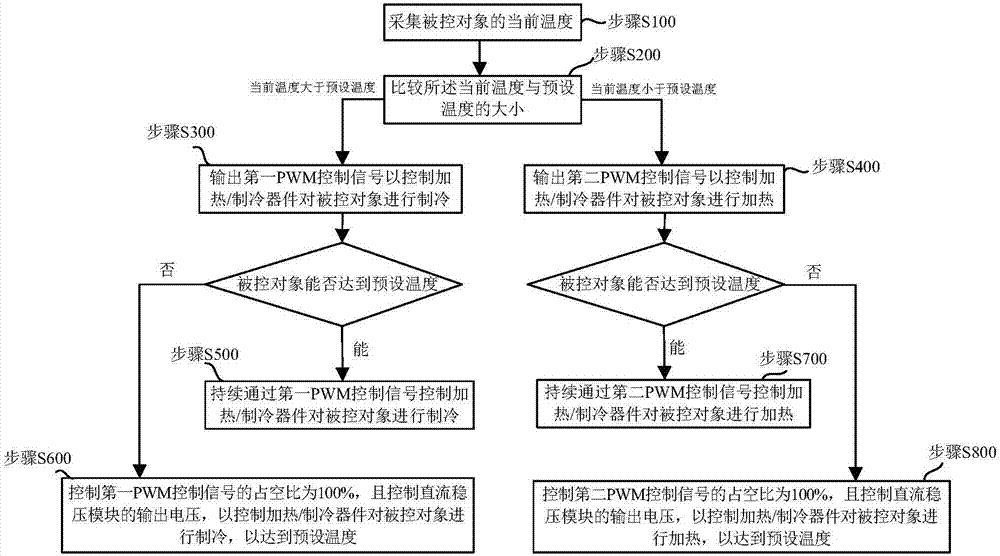
[0026] image 3 It is a flowchart of the temperature control method provided in Embodiment 1 of the present invention. Embodiment 1 of the present invention provides a temperature control method, including the following steps:

[0027] Step S100, collecting the current temperature of the controlled object.

[0028] In this embodiment, the controlled object is a laser device. Those skilled in the art can understand that the controlled object may also be other devices requiring temperature control. A temperature sensor is set on the laser device to collect the current temperature of the laser device.

[0029] Step S200 , comparing the current temperature with the preset temperature, if the current temperature is higher than the preset temperature, go to step S300 ; if the current temperature is lower than the preset temperature, go to step S400 .

[0030] The laser device has its rated operating temperature, which is the preset temperature mentioned above. If the laser device...

Embodiment 2

[0041] Figure 4 It is a flow chart of the temperature control method provided in Embodiment 2 of the present invention. Embodiment 2 of the present invention provides a temperature control method, including the following steps:

[0042] Step S100, collecting the current temperature of the controlled object.

[0043] In this embodiment, the controlled object is a laser device. Those skilled in the art can understand that the controlled object may also be other devices requiring temperature control. A temperature sensor is set on the laser device to collect the current temperature of the laser device.

[0044] Step S210, perform PID calculation according to the deviation between the current temperature and the preset temperature, and obtain the PID calculation value.

[0045] Step S220, compare the PID calculation value with the preset first threshold, if the PID calculation value is greater than or equal to the first threshold, go to step S300; if the PID calculation value i...

Embodiment 3

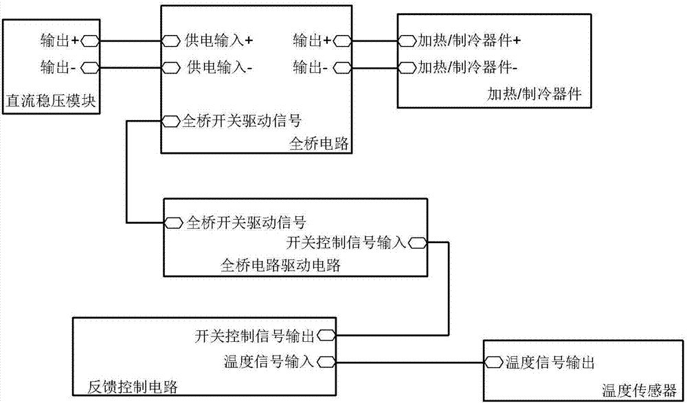
[0066] Figure 5 It is a structural block diagram of the temperature control system provided by Embodiment 3 of the present invention, such as Figure 5 As shown, Embodiment 3 of the present invention provides a temperature control system, including a DC voltage stabilization module, a full bridge circuit, a full bridge circuit drive circuit, a heating / cooling device, a main control module and a temperature sensor set on the controlled object .

[0067] Wherein, the temperature sensor is connected with the input terminal of the main control module, and is used for collecting the current temperature of the controlled object.

[0068] The first PWM control output end of the main control module is connected with the first control input end of the full bridge circuit driving circuit; the second PWM control output end of the main control module is connected with the second control input end of the full bridge circuit driving circuit; The adjustment control terminal of the module ...


PUM


Abstract

The invention provides a temperature control method and a temperature control system to solve the problem that the temperature control circuit is of large volume in the prior art. The method comprises the following steps: collecting the current temperature of a controlled object; if the current temperature is higher than a preset temperature, outputting a first PWM control signal to cool the controlled object; judging whether the temperature of the controlled object can reach the preset temperature; if the temperature of the controlled object can reach the preset temperature, cooling the controlled object constantly; if the temperature of the controlled object cannot reach the preset temperature, enabling the duty ratio of the first PWM control signal to be 100%, and controlling the output voltage of a DC voltage regulator module to cool the controlled object; if the current temperature is lower than the preset temperature, outputting a second PWM control signal to cool the controlled object; judging whether the temperature of the controlled object can reach the preset temperature; if the temperature of the controlled object can reach the preset temperature, cooling the controlled object constantly; and if the temperature of the controlled object cannot reach the preset temperature, enabling the duty ratio of the second PWM control signal to be 100%, and controlling the output voltage of the DC voltage regulator module. The scheme ensures that a heating / cooling device works with high efficiency.

Description

technical field [0001] The invention relates to the field of temperature control of lasers, in particular to a temperature control method and system. Background technique [0002] In the field of laser technology, in order to obtain a laser with a wavelength or a specific output mode, it is usually necessary to use a light source to pump the laser working substance, and through the optical path composed of specific optical devices, the optical transformation of the optical path is performed to achieve the ideal laser output. . Among them, the wavelength of the light source, the laser wavelength generated by the working substance, and the electro-optical efficiency under the same injected energy are all related to the temperature. Therefore, in order to achieve precise control of the output energy and wavelength of the laser, precise temperature control of the temperature-sensitive devices is required. In addition, in some applications, there are strict requirements on the ...

Claims


Application Information

Patent Timeline
IPC IPC(8): G05D23/20
CPCG05D23/20
Inventor 郑毅朱虹吴军勇田晓霞
Owner 11TH RES INST OF CHINA ELECTRONICS TECH GROUP CORP
Why Eureka
Try Eureka