Three-dimensional reconstruction method for defective blade tip of aircraft engine compressor blade

An aero-engine and three-dimensional reconstruction technology, which is applied in the field of robot vision, can solve the problems of not considering the similarity of curves and surfaces, poor extension smoothness, etc., and achieve the effects of easy programming, improved smoothness, and high accuracy

Active Publication Date: 2017-06-20
HEBEI UNIV OF TECH
View PDF7 Cites 15 Cited by
  • Summary
  • Abstract
  • Description
  • Claims
  • Application Information

AI Technical Summary

Problems solved by technology

However, this method does not consider the similarity of curves and surfa

Method used


Image

  • Three-dimensional reconstruction method for defective blade tip of aircraft engine compressor blade
  • Three-dimensional reconstruction method for defective blade tip of aircraft engine compressor blade
  • Three-dimensional reconstruction method for defective blade tip of aircraft engine compressor blade

Examples


Embodiment Construction

[0036] Specific examples of the present invention are given below. The specific embodiments are only used to further describe the present invention in detail, and do not limit the protection scope of the claims of the present application.

[0037] The invention provides a three-dimensional reconstruction method (abbreviation method) of aeroengine compressor blade tip defect, it is characterized in that concrete steps are as follows:

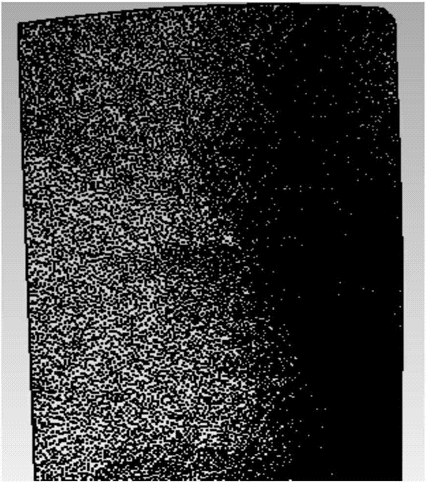
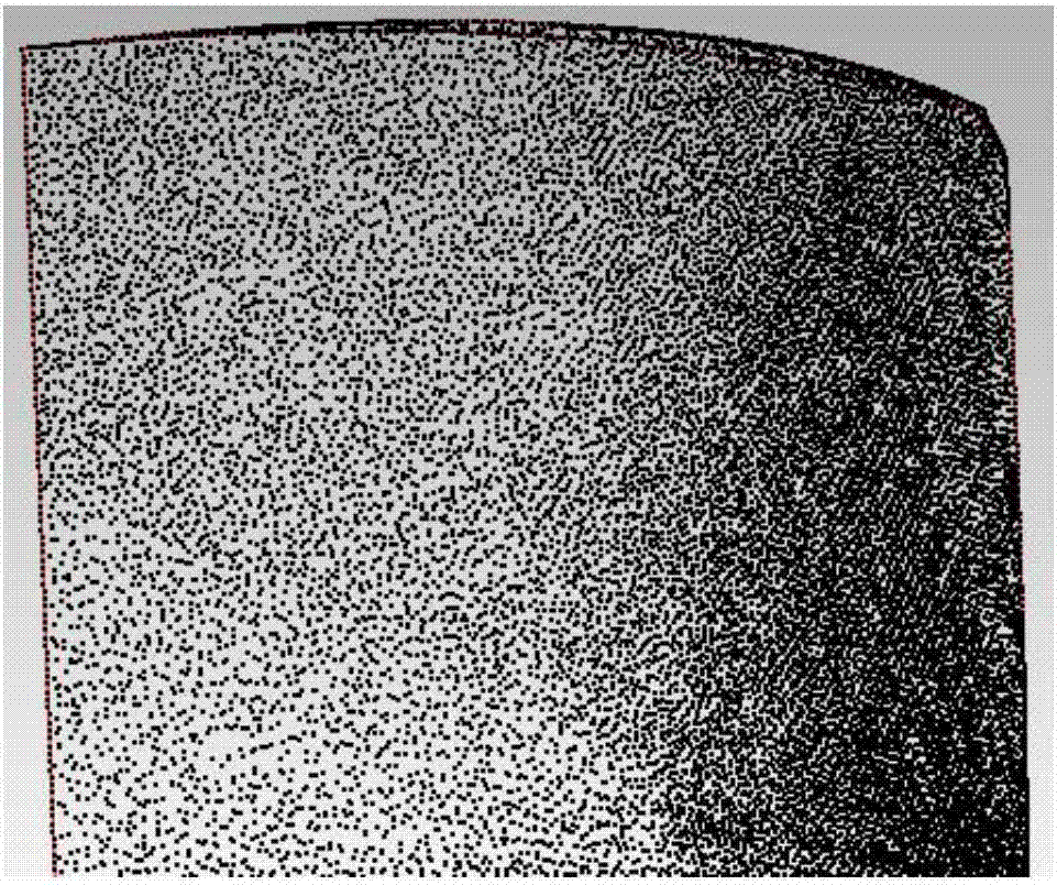
[0038] 1. Optical three-dimensional measurement: select the repairable worn blade, use the optical three-dimensional measurement method to measure the repairable worn blade, and obtain the point cloud of the blade (see figure 1 ); figure 1 Shown in is the point cloud of the data points obtained from the three-dimensional measurement and displayed under the Geomagic Studio software; the specific method is to project sinusoidal fringes to the repairable worn blade to obtain a new relationship between phase and height h'=f(Δφ') and The previousl...


PUM


Abstract

The invention discloses a three-dimensional reconstruction method for a defective blade tip of an aircraft engine compressor blade. The method is characterized by comprising the following steps that 1, a repairable worn blade is measured through an optical three-dimensional measurement method to obtain point clouds of the blade; 2, error point clouds generated in three-dimensional measurement are removed through a smooth filtering method, and the point clouds are simplified through a bounding box method; 3, a maximum value of between-class variance between a boundary point cloud and a curved surface point cloud is calculated by using an Otsu threshold value method for reference, the boundary point cloud and the blade point clouds are distinguished, whether the boundary point cloud is on the boundary of a defectless area or the boundary of a defective area is judged by comparing specific values of principle curvatures, in the two mutually perpendicular directions, of the boundary point cloud, and the obtained boundary point cloud is fit into a boundary line through a least square method; 4, the point clouds of the portions except for the defective portion are fit into a B-Spline curved surface; 5, similarity extension is conducted on the boundary point cloud of the defective area to obtain a complete three-dimensional model. After detection, the similarity measuring value of extension is not larger than 0.2 mm.

Description

technical field [0001] The invention relates to the technical field of robot vision, in particular to a three-dimensional reconstruction method for a blade tip defect of an aeroengine compressor blade. Background technique [0002] With the rapid development of my country's economy, the domestic demand for air travel is also increasing. It is predicted that the number of civil aircraft in my country will reach about 14,000 in 2025. Due to the increasing wear and tear of aircraft components, the number of aircraft to be repaired is also increasing. According to the analysis of the US company TeamSAI, in 2025, the market value of the maintenance of aeroengine compressor blades in my country will reach as high as 1.3 to 1.4 billion US dollars. Due to the immaturity of my country's own repair technology and the technical blockade of key repair technologies abroad, most of the damaged compressor blades that can be repaired in my country are sent to foreign countries for repair. ...

Claims


Application Information

Patent Timeline
IPC IPC(8): G06F17/50G06T17/00
CPCG06F30/15G06F30/20G06T17/00
Inventor 戴士杰宋涛周国霞吕海东
Owner HEBEI UNIV OF TECH
Why Eureka
Try Eureka