Stop band steep dual-notch ultra wide band (UWB) antenna

A double-notch and stop-band technology is applied to antennas, antenna coupling, and devices that enable antennas to work in different bands at the same time. It can solve problems such as unfavorable system integration, difficulty in adjusting the center frequency of stop bands, and large antenna volume. The effect of low cost, compact structure and convenient processing

Inactive Publication Date: 2017-06-20
HARBIN HESON SCI & TECH
View PDF3 Cites 0 Cited by
  • Summary
  • Abstract
  • Description
  • Claims
  • Application Information

AI Technical Summary

Problems solved by technology

However, these methods have limitations, such as the large size of the antenna, which is not conducive to system integration; the center frequency of the stop band is not easy to adjust

Method used


Image

  • Stop band steep dual-notch ultra wide band (UWB) antenna
  • Stop band steep dual-notch ultra wide band (UWB) antenna
  • Stop band steep dual-notch ultra wide band (UWB) antenna

Examples


Embodiment Construction

[0023] The invention designs a double-notch UWB antenna with steep stop bands, and the filter can avoid mutual interference with a WLAN system.

[0024] Below in conjunction with accompanying drawing, invention is described in more detail:

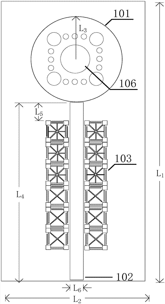
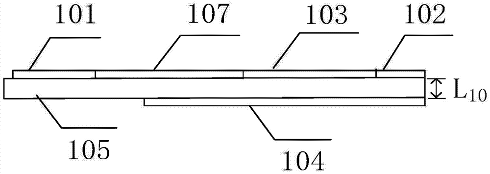
[0025] Such as figure 1 As shown, a double-notch UWB antenna with a steep stop band of the present invention, the radiation unit (101) on the dielectric substrate, the impedance matching input microstrip line (102), the circular etched fractal structure (106), and the rice character The cross-type EBG electromagnetic bandgap structure (107), the cross-type EBG electromagnetic bandgap structure (103), adopts copper material.

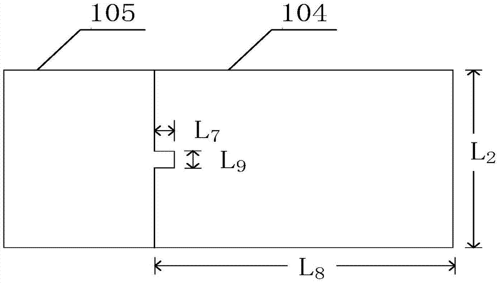
[0026] An example of the present invention is figure 2 As shown, the dielectric substrate (105) is a GML1000 material with a dielectric constant of 3.2. The dielectric substrate has a thickness of 0.762mm.

[0027] The metal grounding plate (104) under the dielectric substrate is made of copper material.

[0028...


PUM


Abstract

A stop band steep dual-notch UWB antenna relates to a UWB band-stop antenna of which the notch frequency band is located at the WLAN and RFID frequency bands, and is composed of a dielectric substrate (105), a radiation unit (101) on the dielectric substrate, an impedance matching input microstrip line (102), a cross-shaped electromagnetic band gap (EBG) structure (103), an EBG structure (107) shaped like a Chinese character mi and a metal grounding plate (104) under the dielectric substrate. The stop band steep dual-notch UWB antenna of the present invention realizes the passband bandwidth required by the UWB by utilizing the radiation unit, the impedance matching input microstrip line and the metal grounding plate, utilizes the circular radiation unit with a circular fractal structure to improve the stop band attenuation inhibition, and utilizes the EBG structures to realize the band stop characteristic. The stop band of the antenna involved in the present invention is nearby 5.2 GHz and 6.8 GHz, thereby avoiding the mutual interference of a WLAN system and an RFID system.

Description

technical field [0001] The invention relates to a UWB band stop antenna, in particular to a double-notch UWB antenna with a steep stop band, which can suppress the mutual interference problem of a WLAN system (5.15-5.35 GHz). Background technique [0002] In February 2002, the US Federal Communications Commission (FCC) approved the 3.1-10.6GHz frequency band for commercial communications, so UWB is widely used. [0003] However, due to the wide frequency band covered by UWB communication, some frequency bands share frequency band resources with other wireless systems, and may interfere with other systems, such as Wimax system (3.2-3.5GHz), WLAN system (5.15-5.35GHz), ( 5.725-5.825GHz) and RFID systems (6.8GHz). How to solve co-channel interference has become an important content of UWB research, so ultra-wideband antennas with stopband characteristics have high practical value. [0004] In recent years, there have been many design ideas for UWB bandstop antennas, such as s...

Claims


Application Information

Patent Timeline
Patent Type & Authority Applications(China)
IPC IPC(8): H01Q5/25H01Q1/52H01Q1/38H01Q1/36
Inventor 郝术苗耿一方高爽
Owner HARBIN HESON SCI & TECH
Why Eureka
Try Eureka