Three-degree-of-freedom permanent-magnet spherical motor

A motor and degree of freedom technology, applied in synchronous motors with static armatures and rotating magnets, electric components, magnetic circuit rotating parts, etc., can solve the deterioration of dynamic performance of spherical motors with friction torque, and limit the development of miniaturization of spherical motors , occupying the installation space of the stator coil, etc., to achieve the effect of simplifying the processing, improving the temperature rise problem, and improving the heat dissipation capacity

Inactive Publication Date: 2017-06-20
TIANJIN UNIV
View PDF8 Cites 15 Cited by
  • Summary
  • Abstract
  • Description
  • Claims
  • Application Information

AI Technical Summary

Problems solved by technology

[0007] In 2009, Anhui University proposed to install the ball support on the top and the bottom. Although this method also does not have the problem of eccentricity, since it needs to install ring-shaped balls, it occupies the installation space of the stator coil and affects the movement angle of the rotor. Limits the miniaturization development of spherical motors
[0009] In 2008, Tianjin University proposed a support structure with annular arc surface contact. Patent CN200810053083.5 discloses a three-degree-of-freedom Halbach array permanent magnet spherical synchronous motor. This structure also does not have the problem of eccentricity, but the friction torque is relatively large. Although the motion error is reduced by adding lubricant and other measures, its friction torque is still the main reason for the deterioration of the dynamic performance of the spherical motor

Method used


Image

  • Three-degree-of-freedom permanent-magnet spherical motor
  • Three-degree-of-freedom permanent-magnet spherical motor
  • Three-degree-of-freedom permanent-magnet spherical motor

Examples


Embodiment Construction

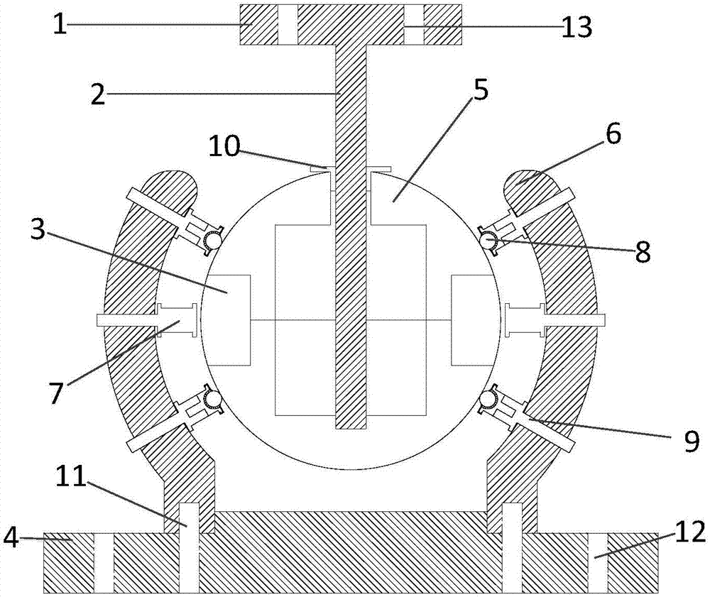
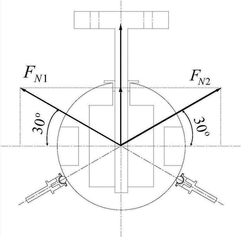
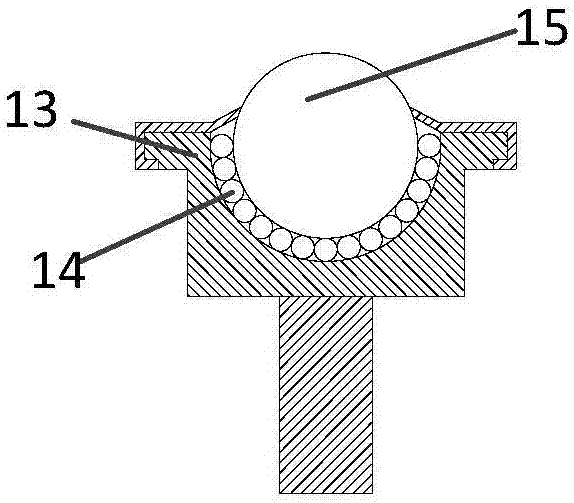
[0026] The present invention proposes a three-degree-of-freedom permanent magnet spherical motor supported by universal balls, including a base 4, universal balls 8, a spherical rotor body 5, an output shaft 2, a stator coil 7, an outer stator 6, an output shaft 2, Flange 1 etc., wherein the rotor 5 is two hollow hemispheres made of aluminum to reduce the moment of inertia of the spherical motor, wherein the upper and lower rotor hemispheres are fixed by tightening bolts and the output shaft. A cylindrical groove 3 is provided at the equator of the rotor for inlaying permanent magnets, and resin is used to seal the gap. Four universal balls 8 are evenly installed on the combined stator coil frame 9 to support the rotor 5. The universal balls 8 are of SP15-FL type, and the eight supporting points are respectively located at the vertices of the cuboid. By adopting the universal ball to support the rotor, the frictional force during the operation of the spherical motor can be sig...


PUM


Abstract

The invention relates to a three-degree-of-freedom permanent-magnet spherical motor. The three-degree-of-freedom permanent-magnet spherical motor comprises a base 4, a stator shell 6, universal balls 8, a spherical rotor body 5, an output shaft 2 and stator coils 7, wherein the stator shell 6 is fixed on the base 4, a rotor 5 is of a spherical shape and is fixedly connected with the output shaft 2, a cylindrical groove is formed in an equator position of the rotor and is used for embedding a permanent magnet, threaded holes are formed in the stator shell 6, a part of threaded holes are used for fixing the stator coils 7 by stator coil frames, the other part of threaded holes are used for fixing the stator coils 7 by combined stator coil frames 9, each combined stator coil frame 9 is in threaded connection with the universal ball 8 used for supporting the rotor, each universal ball 8 comprises a support tray 13, the support tray 13 is in threaded connection with the combined stator coil frame 9, a steel ball 14 is arranged in the support tray, and a nylon ball 15 is arranged on the steel ball 14.

Description

technical field [0001] The invention relates to a spherical motor capable of realizing multi-degree-of-freedom motion, and belongs to the technical field of motor design. Background technique [0002] Traditionally, to achieve multi-degree-of-freedom motion, multiple motors are required to cooperate, which not only makes the motor structure complex and bulky, but also has poor dynamic performance and low control precision. Spherical motors emerged as the times require. Compared with traditional multi-degree-of-freedom motors, they have the advantages of high magnetic energy product, high operating efficiency, small size, and good controllability. They are widely used in radars, panoramic cameras, robotic arms and other fields. With the development of power electronics, computer control and manufacturing materials, these provide a solid foundation for the manufacture and control of spherical motors. [0003] At present, the existing support mechanisms mainly include the foll...

Claims


Application Information

Patent Timeline
Patent Type & Authority Applications(China)
IPC IPC(8): H02K21/14H02K1/27H02K3/46H02K1/20
CPCH02K21/14H02K1/20H02K1/276H02K3/46
Inventor 李洪凤林康
Owner TIANJIN UNIV
Why Eureka
Try Eureka