Rana spinosa feeding device

A technology of stone frogs and racks, which is applied in transportation and packaging, conveyors, animal husbandry, etc., can solve the problems of difficult perception of bait and poor feeding effect of stone frogs, and achieve good feeding effect, convenient predation, and small weight Effect

Active Publication Date: 2017-06-23
贵州习源岭养殖有限公司
View PDF12 Cites 1 Cited by
  • Summary
  • Abstract
  • Description
  • Claims
  • Application Information

AI Technical Summary

Problems solved by technology

[0005] The present invention intends to provide a stone frog feeding device to solve the problems in the prior art that the bait is not easily perceived by the stone frog and the feeding effect of the stone frog is not good

Method used


Image

  • Rana spinosa feeding device
  • Rana spinosa feeding device

Examples


Embodiment 1

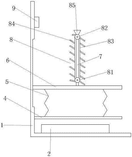
[0030] Such as figure 1 , figure 2 As shown, the stone frog feeding device includes a frame 1. The frame 1 is sequentially provided with a magnetic field generating mechanism 2, a support plate 4 and a supporting plate 6 from bottom to top. The magnetic field generating mechanism 2 is connected to a power supply, and the supporting plate 6 is a magnet. The support plate 4 is fixedly connected with the frame 1, and the support plate 6 is slidingly connected with the frame 1; four elastic members 5 are arranged between the support plate 6 and the support plate 4, and the elastic members 5 are compression springs, return springs, or rubber One of the rings, the low end of the elastic member 5 is connected to the support plate 4, the high end of the elastic member 5 is connected to the supporting plate 6, and the elastic members 5 are respectively located at the four ends of the supporting plate 4 and the supporting plate 6, and the supporting plate 6 is provided with a support ...

Embodiment 2

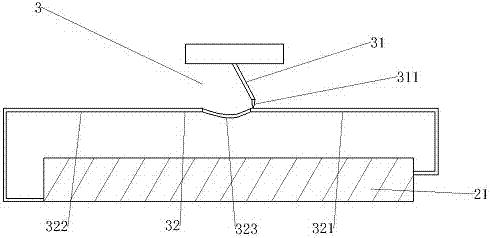
[0034] The difference from Embodiment 1 is that the electromagnet 21 is connected with a current control mechanism 3, the current control mechanism 3 includes a conductive rod 31 and a conductive wire 32 connected to the power supply, and the free end of the conductive rod 31 is hinged with a conductive needle 311, The conductive wire 32 includes a first conductive end 321, a second conductive end 322 and an insulated end 323 between the first conductive end 321 and the second conductive end 322. The first conductive end 321 and the second conductive end 322 are connected to the electromagnet respectively. The two ends of 21 are connected.

[0035] When in use, the electromagnet 21 generates a magnetic field through the connection between the conductive needle 311 and the first conductive end 321, and pushes the pallet 6 to move upward. As the electromagnet 21 generates a magnetic field, the magnetic field and the right end of the conductive needle 311 repel each other, so it i...


PUM


Abstract

The invention belongs to the technical field of batrachia breeding device, and discloses a rana spinosa feeding device. The rana spinosa feeding device comprises a stand, wherein a supporting plate is arranged on the stand; a magnetic field generation mechanism is arranged below the supporting plate; the magnetic field generation mechanism is connected with a power supply; a position, which is located above the supporting plate, on the stand is connected with a magnetic carrying plate in a sliding manner; elastic pieces are arranged between the carrying plate and the supporting plate; one end of each elastic piece is connected with the supporting plate, and the other end of the elastic piece is connected with the carrying plate; a supporting frame is arranged on the carrying plate; a material bearing mechanism is arranged on the supporting frame; the material bearing mechanism comprises a driving roller arranged at the bottom of the supporting frame and a driven roller arranged at the top of the supporting frame; the driving roller is connected with a transmission motor; a power control valve is arranged on the transmission motor; a transmission belt is arranged on the driving roller and the driven roller; a plurality of material trays are arranged on the transmission belt; a sensor is arranged at the top of the stand. The rana spinosa feeding device solves the problems that rana spinosa cannot sense baits easily, and the rana spinosa feeding effect is poor in the prior art.

Description

technical field [0001] The invention belongs to the field of frog feeding devices, in particular to a stone frog feeding device. Background technique [0002] The stone frog, also known as the spiny-chested frog, is a kind of animal in the family Ranaidae of the order Anura. The stone frog has delicious meat, fast growth and large size, and has the effects of invigorating the spleen and eliminating accumulation, nourishing and strengthening, so it is widely eaten by people. For supplying people's demand, present stone frog is mainly based on artificial feeding, adopts the mode of feeding feed during feeding. Due to the visual characteristics of the stone frog, it can only prey on the moving bait, so the existing feeding machine mainly has two design principles: one is the vibration principle to drive the bait to move, and the other is the stirring method to drive the bait to move. If the bait is driven by the vibration principle, the bait will produce noise during the vibr...

Claims


Application Information

Patent Timeline
Patent Type & Authority Applications(China)
IPC IPC(8): A01K67/02B65G54/02
CPCA01K67/02B65G54/02
Inventor 罗春袁勤
Owner 贵州习源岭养殖有限公司
Why Eureka
Try Eureka