Precisely controlled intelligent four-rotor unmanned aerial vehicle

A quadrotor unmanned aerial vehicle, an intelligent technology, applied in the field of unmanned aerial vehicles, can solve the problems of ensuring the rotating speed of the rotors, difficult flying operation of the unmanned aerial vehicle, low control accuracy, etc., and achieve the effect of precise operation

Inactive Publication Date: 2017-06-23
江西中轻智能设备有限公司
View PDF4 Cites 8 Cited by
  • Summary
  • Abstract
  • Description
  • Claims
  • Application Information

AI Technical Summary

Problems solved by technology

[0003] As a flying device, existing UAVs usually have the problem of low control accuracy. The main reason is that UAVs are usually affected by wind interference during outdoor flight. In the vertical direction, the wind produces upward buoyancy or downward force on the UAV, making it difficult for the UAV to maintain a horizontal flight operation. Not only that, when the UAV is flying, it usually relies on the driving motor to drive the blades to rotate to generate buoyancy. The existing UAV is usually a quadrotor UAV. By controlling the speed of the motor in the four directions, the vertical, Pitch, roll, yaw, forward and backward, and sideways movement, but in the process of motor driving, there are high requirements for the driving accuracy of the motor. It is necessary to accurately control the rotation speed of the rotor to complete the actions required by the user. Because the driving motor is difficult Correctly ensure the rotation speed of the rotor, so that in the actual operation process, it is difficult for the user to accurately control the movement of the drone

Method used


Image

  • Precisely controlled intelligent four-rotor unmanned aerial vehicle
  • Precisely controlled intelligent four-rotor unmanned aerial vehicle
  • Precisely controlled intelligent four-rotor unmanned aerial vehicle

Examples


Embodiment Construction

[0032] The present invention is described in further detail now in conjunction with accompanying drawing. These drawings are all simplified schematic diagrams, which only illustrate the basic structure of the present invention in a schematic manner, so they only show the configurations related to the present invention.

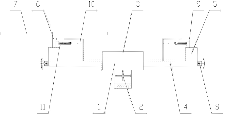
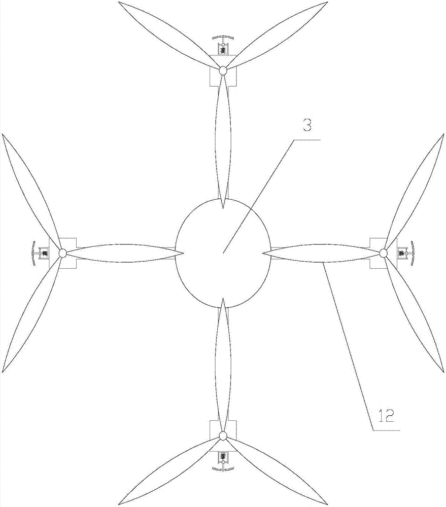
[0033] Such as Figure 1-Figure 6 As shown, an intelligent four-rotor UAV with precise control includes a main body 1, a deflection measurement mechanism 2 arranged under the main body 1, and several flying units 12, and the flying units 12 are evenly distributed on the outer periphery of the main body 1 in the circumferential direction. ;

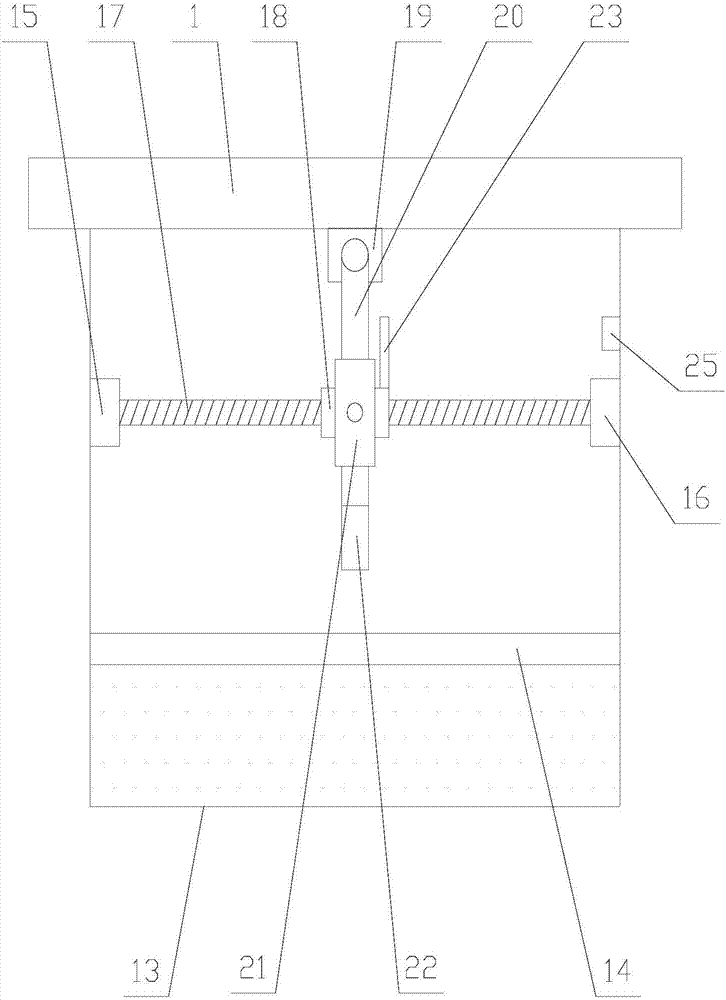
[0034] The deflection measurement mechanism 2 includes a housing 13, the bottom of the housing 13 is provided with an aqueous solution, the housing 13 is provided with a reflector 14 and a deflection measurement assembly, the reflector 14 floats on the aqueous solution, and the deflection measurement The assembly is arra...


PUM


Abstract

The invention relates to a precisely controlled intelligent four-rotor unmanned aerial vehicle. The precisely controlled intelligent four-rotor unmanned aerial vehicle comprises a deflection measuring mechanism and a plurality of flight units; the deflection measuring mechanism comprises a light reflecting plate and a deflection measuring assembly; the deflection measuring assembly comprises a driving unit, a moving block, a hinge block, a rotating rod, a sleeve and a first photoelectric sensor; each flight unit comprises an auxiliary speed measurement unit on a side rod and a speed reducing unit on a first driving shaft; each auxiliary speed measurement unit comprises a supporting rod, a resistance rod, a transverse rod and a second photoelectric sensor; according to the precisely controlled intelligent four-rotor unmanned aerial vehicle, the inclination degree of an unmanned aerial vehicle is accurately controlled through the deflection measuring mechanism, the rotating speed of the first driving shaft in each flight unit is detected through the corresponding auxiliary speed measurement unit, and a speed is reduced to different degrees by utilizing the speed reducing unit, so that each flight unit is regulated to keep the unmanned aerial vehicle horizontal; the wind strength in each direction is detected through a wind detecting unit; the rotating speed of paddles in each flight unit is regulated again; therefore, precise operation of the unmanned aerial vehicle is realized.

Description

technical field [0001] The invention relates to the field of unmanned aerial vehicles, in particular to an intelligent four-rotor unmanned aerial vehicle with precise control. Background technique [0002] Unmanned aerial vehicle, unmanned aerial vehicle (UAV) for short, is a new concept weapon equipment in rapid development, which has the advantages of flexible maneuvering, quick response, unmanned flight, and low operation requirements. UAVs equipped with multiple types of sensors can realize real-time image transmission and detection of high-risk areas, which is a powerful supplement to satellite remote sensing and traditional aerial remote sensing. At present, the scope of use of UAVs has been expanded to the three major fields of military, scientific research, and civilian use, specifically in power, communications, meteorology, agriculture, ocean, exploration, photography, disaster prevention and reduction, crop production estimation, anti-drug anti-smuggling, border p...

Claims


Application Information

Patent Timeline
Patent Type & Authority Applications(China)
IPC IPC(8): B64C27/08B64C27/14B64C19/00B64D43/00
CPCB64C19/00B64C27/08B64C27/14B64D43/00B64U10/10B64U50/19B64U2201/00
Inventor 陈科
Owner 江西中轻智能设备有限公司
Why Eureka
Try Eureka