Supercharge Your Innovation With Domain-Expert AI Agents!

Buried pipe optimization method and system based on seasonal energy storage

An optimization method and technology for buried pipes, applied in design optimization/simulation, special data processing applications, instruments, etc., can solve problems such as increased drilling costs, small soil thermal conductivity, and large distance between buried pipes.

Inactive Publication Date: 2017-06-23
GREE ELECTRIC APPLIANCES INC
View PDF1 Cites 2 Cited by
  • Summary
  • Abstract
  • Description
  • Claims
  • Application Information

AI Technical Summary

Problems solved by technology

[0003] (1) The distance between the buried pipes is large and the thermal conductivity of the soil is small, so that the energy of the soil at a long distance cannot be fully utilized, which indirectly causes the problem that the buried pipe occupies too much area;
[0004] (2) When the vertical buried pipe is arranged, the borehole is deep, and the heat transfer temperature difference between the fluid and the soil deep in the pipe is gradually reduced, which makes the design of too much buried depth not meaningful, and greatly increases the drilling cost, especially Under the complex geological structure, the cost of drilling accounts for almost half of the total investment
Although the existing optimization scheme can improve the above problems to some extent, it lacks versatility and cannot fundamentally solve the above problems of high drilling costs and large land occupation

Method used


Image

  • Buried pipe optimization method and system based on seasonal energy storage
  • Buried pipe optimization method and system based on seasonal energy storage
  • Buried pipe optimization method and system based on seasonal energy storage

Examples


Embodiment Construction

[0089] The technical solutions of the present invention will be described in further detail below with reference to the accompanying drawings and embodiments.

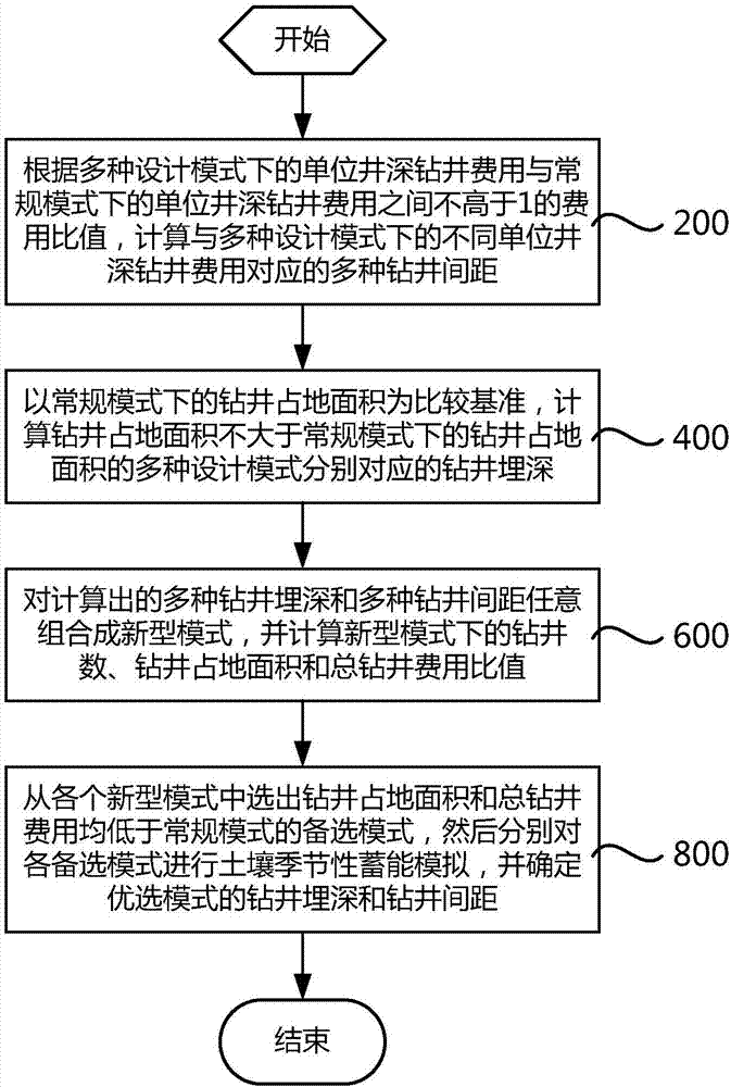
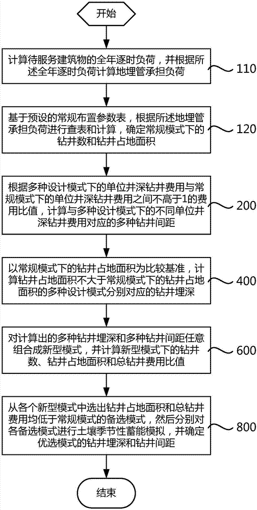
[0090] like figure 1 As shown, it is a schematic flowchart of an embodiment of the method for optimizing buried pipes based on seasonal energy storage in the present invention. In this embodiment, the buried pipe optimization method based on seasonal energy storage includes:

[0091] Step 200, according to the cost ratio between the drilling cost per well depth in various design modes and the drilling cost per well depth in the conventional mode, which is not higher than 1, calculate the corresponding multi-drilling costs for different unit depths in various design modes Drilling spacing;

[0092] Step 400, taking the drilling footprint in the conventional mode as a comparison reference, calculating the drilling depths corresponding to the various design modes whose drilling footprint is not larger than the drilling ...


PUM


Abstract

The invention relates to a buried pipe optimization method and system based on seasonal energy storage. The method includes the steps that according to the expanse ratio, not higher than 1, between the unit well depth drilling expanses under multiple design modes and the unit well depth drilling expanse under a conventional mode, multiple drilling gaps corresponding to different drilling expanses are calculated; with the drilling occupied area under the conventional mode as the comparison criterion, drilling burial depths corresponding to the design modes with the drilling occupied areas not larger than the drilling occupied area under the conventional mode are calculated; the obtained burial depths and the drilling gaps are arbitrarily combined into new modes, and the drilling quantities, the drilling occupied areas and the total drilling expense ratio under the new modes are calculated; alternative modes with the drilling occupied areas and the total drilling expenses lower than the drilling occupied area and the total drilling expense under the conventional mode are selected from the new modes, soil seasonal energy storage simulation is carried out on the alternative modes, and the drilling burial depth and the drilling gap under an optimal mode are determined. By means of the buried pipe optimization method and system based on seasonal energy storage, the drilling initial investment and the pipe burying occupied area are reduced, and the soil seasonal energy storage requirement is met.

Description

technical field [0001] The invention relates to the field of heat pump construction, in particular to a method and system for optimizing buried pipes based on seasonal energy storage. Background technique [0002] The ground source heat pump system is a device that uses the relatively stable temperature of the underground normal temperature soil to complete heat exchange with the interior of the building through the pipeline system buried deep around the building. In winter, it takes heat from the soil to heat the building; in summer, it discharges heat to the soil to cool the building. At present, the existing ground source heat pump system has the following problems: [0003] (1) The distance between the buried pipes is large and the thermal conductivity of the soil is small, so that the energy of the soil at a long distance cannot be fully utilized, which indirectly causes the problem that the buried pipe occupies too much area; [0004] (2) When the vertical buried pip...

Claims


Application Information

Patent Timeline
Patent Type & Authority Applications(China)
IPC IPC(8): G06F17/50
CPCG06F30/13G06F30/20G06F2113/14
Inventor 杨慧斌余延顺谢文利
Owner GREE ELECTRIC APPLIANCES INC
Features
  • R&D
  • Intellectual Property
  • Life Sciences
  • Materials
  • Tech Scout
  • Unparalleled Data Quality
  • Higher Quality Content
  • 60% Fewer Hallucinations
Learn More