
Electric vehicle charging pile cooling cable

A technology for electric vehicles and charging piles, applied in the field of power cables, can solve problems such as limited heat dissipation and cooling effects, small heat transfer area, damage to cables and charging equipment, etc.

Inactive Publication Date: 2017-06-23
江苏诸成电缆有限公司
View PDF6 Cites 36 Cited by
  • Summary
  • Abstract
  • Description
  • Claims
  • Application Information

AI Technical Summary

Problems solved by technology

Its structure is nothing more than two types: one is that the charging conductor is adjacent to the cooling medium conduit and is independently arranged, such as a cooling conduit is arranged adjacent to one side or both sides of the charging conductor. This structure realizes charging through indirect heat transfer. Conductor heat dissipation and cooling, the heat dissipation and cooling effect is limited, and cannot meet the development requirements of high-current and high-power charging cables in the future; the other type is to install the cooling conduit through the core of the charging conductor for direct heat transfer, and its heat dissipation effect is obviously better. Compared with the previous type of heat dissipation structure, but this kind of direct heat conduction structure, because the cooling conduit is limited to the charging conductor, on the one hand, the cooling medium flow section of the cooling conduit is small, and the flow rate and velocity are greatly restricted; on the other hand, the conductor and the conduit The heat transfer area between them is small; and because the cooling conduit is located in the charging conductor, during the dragging and moving process of the charging cable, the charging conductor on the outer layer will squeeze and bend the conduit, which will easily cause the bending of the cooling conduit Blockage, loss of cooling effect, but will accelerate the damage of cables and charging equipment

Method used


Image

  • Electric vehicle charging pile cooling cable

Examples


Embodiment Construction

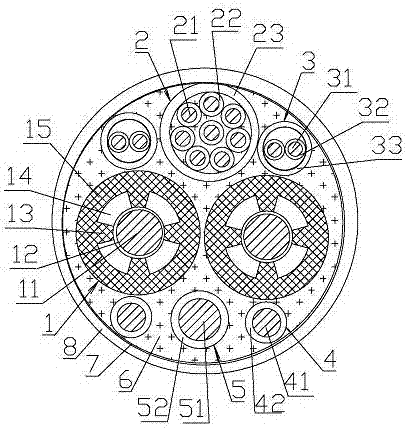
[0019] Such as figure 1 As shown in the electric vehicle charging pile cooling cable, the cable core of the cooling cable consists of two power cables 1, one ground wire 5, two auxiliary power cables 4, two signal cables 3 and one control cable 2 composition. The cable core is filled with a filler 6, which is a highly flame-resistant PP mesh filler rope, and of course it can also be a hydrophobic filler or other commonly used cable core filler materials; the above structure makes the power cable 1, ground The wires 5, auxiliary power cables 4, signal cables 3 and control cables 2 are all buried in the filler 6 and surrounded by the filler material. A tape layer 7 is covered outside the cable core, and a cable outer sheath 8 is extruded on the tape layer 7 . In this implementation, the tape layer 7 is a non-woven tape layer, and the cable outer sheath 8 is extruded from a low-smoke halogen-free cable sheath material.

[0020] The power cable 1 includes a power cable conducto...


PUM


Abstract

The present invention discloses an electric vehicle charging pile cooling cable. The electric vehicle charging pile cooling cable comprises a cable core and a cable outer sheath covering the cable core; the cable core comprises power cables, a ground wire and auxiliary power cables; the cable core further comprises a control cable and / or signal cables; the power cable includes a power cable conductor and a power cable insulation layer; cooling cavity support ribs are arranged between the power cable conductor and the power cable insulation layer; the power cable insulation layer, the cooling chamber support ribs and the power cable conductor enclose cooling cavities for conveying a cooling liquid; the cooling cavities surround the outer periphery of the power cable conductor and are disposed along the length of the power cable conductor; a plurality of metal conductor wires are stranded and bunched so as to form the power cable conductor; and the power cable conductor is provided with a wire harness armoring layer. The electric vehicle charging pile cooling cable has the advantages of good heat dissipation effect, high flexibility and light weight, and can effectively reduce current heat and achieve high-power charging.

Description

technical field [0001] The invention relates to the technical field of power cables, in particular to a charging cable for a charging pile for a new energy vehicle. Background technique [0002] New energy electric vehicles have many advantages such as high efficiency, energy saving, and zero emissions, and they are becoming more and more popular. To ensure the normal operation of new energy electric vehicles, infrastructure such as charging stations, charging piles and charging power cables are essential. [0003] Charging speed is an important factor affecting the development of new energy electric vehicles. High-current and high-voltage cables are the future development direction. High-power charging can greatly shorten the charging time and reduce charging waiting. Therefore, cars need to use more and more charging current. . However, high-current and high-power charging will inevitably bring about cable heating and high temperature rise. Excessive cable temperature ri...

Claims


Application Information

Patent Timeline
IPC IPC(8): H01B7/04H01B7/17H01B7/42H01B9/00
CPCH01B7/041H01B7/17H01B7/423H01B9/003B60L53/18Y02T10/70Y02T10/7072Y02T90/14
Inventor 朱汉青陈渊朱华倩陈灯明柳磊
Owner 江苏诸成电缆有限公司
Learn More