Horizontal injection press

An injection molding machine, horizontal technology, applied in the field of horizontal injection molding machines, can solve the problems of reduced mold clamping efficiency, influence of injection molding efficiency, and low injection quality, and achieve the effects of improving mold clamping accuracy, injection efficiency, and injection quality.

Inactive Publication Date: 2017-06-27
嘉善优联物流装备有限公司
View PDF3 Cites 3 Cited by
  • Summary
  • Abstract
  • Description
  • Claims
  • Application Information

AI Technical Summary

Problems solved by technology

In the existing horizontal injection molding machine, the first half-mold and the second half-mold of the mold body are respectively fixed on the moving plate and the fixed plate, and the mold body is molded by moving the moving plate to carry out injection molding. However, the injection molding process in this way In one injection molding operation, only one mold body can be injected, and the injection molding efficiency is quite low
The movement of the moving plate is driven by the driving mechanism, which drives the moving plate and moves horizontally with the moving plate. Because the weight of the moving plate and half mold itself is very large, and the weight of the driving motor makes the driving motor drive the moving plate. At the same time as the half mold, it must drive its own weight to carry out the operation, which undoubtedly increases the power consumption of the driving mechanism, and at the same time greatly reduces the mold clamping efficiency of th

Method used


Image

  • Horizontal injection press
  • Horizontal injection press
  • Horizontal injection press

Examples


Embodiment Construction

[0024] In order to make the technical means, creative features, goals and effects achieved by the present invention easy to understand, the present invention will be further described below in conjunction with specific embodiments.

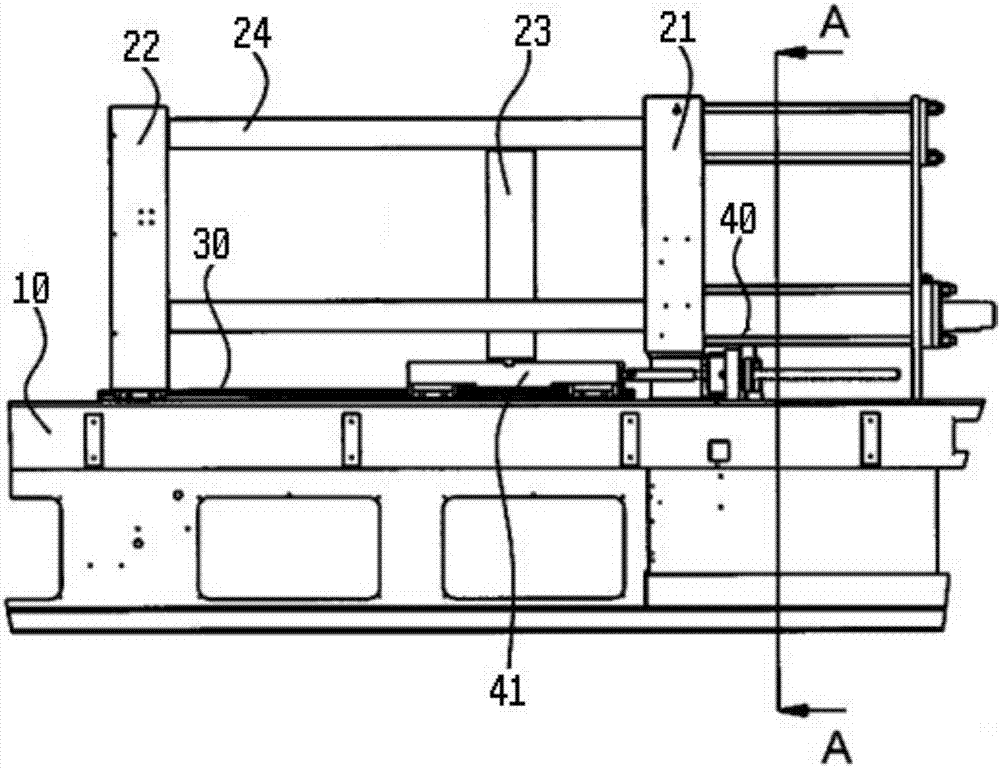
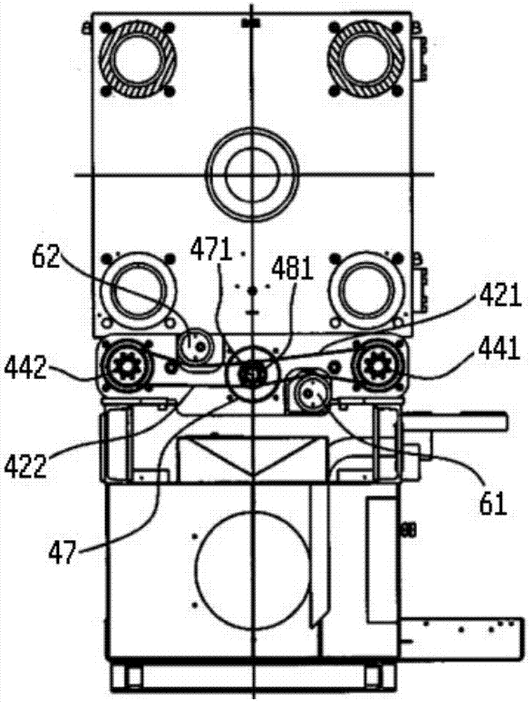
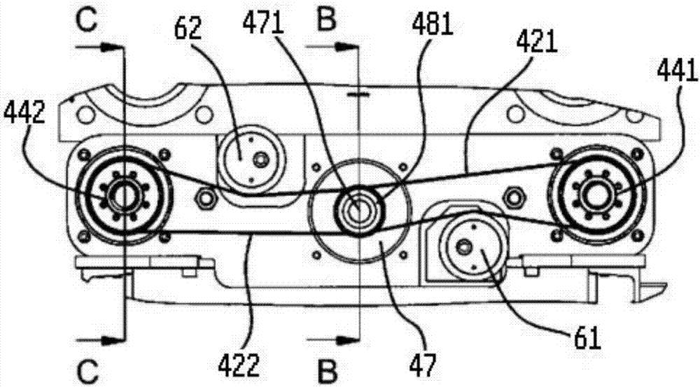
[0025] see Figure 1 to Figure 7, a horizontal injection molding machine described in the present invention includes a workbench 10 and an injection molding mechanism located on the workbench 10, a fixed platen 21, a movable platen 22, a mold frame plate 23, a horizontal drive mechanism 40, guide rails 30 and several guide post 24. The guide post 24 is arranged horizontally and its two ends are respectively connected with the fixed platen 21 and the movable platen 22 . The formwork plate 23 is disposed between the fixed platen 21 and the movable platen 22 and is slidably sleeved on the guide post 24 . The moving platen 22 is disposed on the guide rail 30 , and there are four guide posts 24 that pass through the moving platen 22 . The moving plat...


PUM


Abstract

The invention discloses a horizontal injection press which comprises a working table, an injection molding mechanism, a fixed pressing plate, a movable pressing plate, a formwork plate, a horizontal driving mechanism, a guide rail and a plurality of guide columns; the movable pressing plate and the formwork plate slide in the extending direction of the guide columns, and the horizontal driving mechanism comprises a sliding table, a first transmission belt, a second transmission belt, a first connecting rod, a second connecting rod, a first main shaft nut, a second main shaft nut, a first driven belt wheel, a bearing plate, at least one driving motor, a driving sliding wheel, a first main shaft with an external thread and a second main shaft with an external thread; and the bearing plate and the driving motor are fixedly arranged on the working table, and the sliding table is arranged on the guide rail in a horizontally-sliding manner. The horizontal injection press is simple in structure and low in cost, the die opening and closing accuracy is high, multiple dies can be subject to injection molding through one-time injection molding operation, the injection molding efficiency is high, and the injection molding quality is good.

Description

technical field [0001] The invention relates to the field of injection molding machines, in particular to a horizontal injection molding machine. Background technique [0002] In the production process of steel structure products, plastic castings such as plastic handles and buttons will be used, and plastic castings need to be injected by injection molding machines. Injection molding machine, also known as injection molding machine or injection machine, is the main molding equipment for making thermoplastics or thermosetting plastics into various shapes of plastic products using plastic molding molds. It is divided into vertical, horizontal, and all-electric types. The horizontal injection molding machine has a short body and is easy to operate and maintain; the center of gravity of the machine is low and the installation is relatively stable; after the product is ejected, it can automatically fall by gravity, which is easy to realize fully automatic operation, so it is fav...

Claims


Application Information

Patent Timeline
IPC IPC(8): B29C45/84B29C45/66B29C45/20B29C45/78
CPCB29C45/20B29C45/66B29C45/78B29C45/84B29C2945/7604
Inventor 陆益
Owner 嘉善优联物流装备有限公司
Why Eureka
Try Eureka