A Total Internal Reflection Fluorescence Microscope Combined with Atomic Force Microscope

An atomic force microscope and fluorescence microscope technology, applied in the field of optical microscopes, can solve the problems of the latter being unable to place optical microscopes, the structural compatibility and matching of total internal reflection fluorescence microscopes are poor, and they will not be considered, so as to meet the needs of optical imaging, It is convenient for large-scale promotion and application, and the effect of good compatibility

Active Publication Date: 2019-05-14
IPE BIOTECHNOLOGY CO LTD
View PDF7 Cites 0 Cited by
  • Summary
  • Abstract
  • Description
  • Claims
  • Application Information

AI Technical Summary

Problems solved by technology

[0004] However, the inventor found that the total internal reflection fluorescence microscope provided by the prior art has a large volume and poor flexibility in the structure of each component.
When it is used in combination with AFM, its structural compatibility and matching with AFM will have some problems as shown below: For example, the gap between the sample stage on an inverted optical microscope and the bright field illumination condenser The distance must be greater than the height of the AFM scan head itself, otherwise the latter cannot be placed on the optical microscope
At present, the sample stages of most atomic force microscopes generally do not take the above problems into consideration.
As a result, the structural compatibility and matching between the total internal reflection fluorescence microscope and the atomic force microscope will be poor.

Method used


Image

  • A Total Internal Reflection Fluorescence Microscope Combined with Atomic Force Microscope
  • A Total Internal Reflection Fluorescence Microscope Combined with Atomic Force Microscope
  • A Total Internal Reflection Fluorescence Microscope Combined with Atomic Force Microscope

Examples


Embodiment Construction

[0054] In order to make the object, technical solution and advantages of the present invention clearer, the implementation manner of the present invention will be further described in detail below in conjunction with the accompanying drawings.

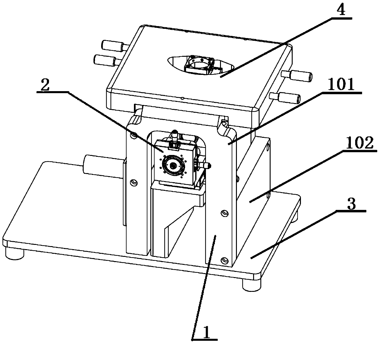
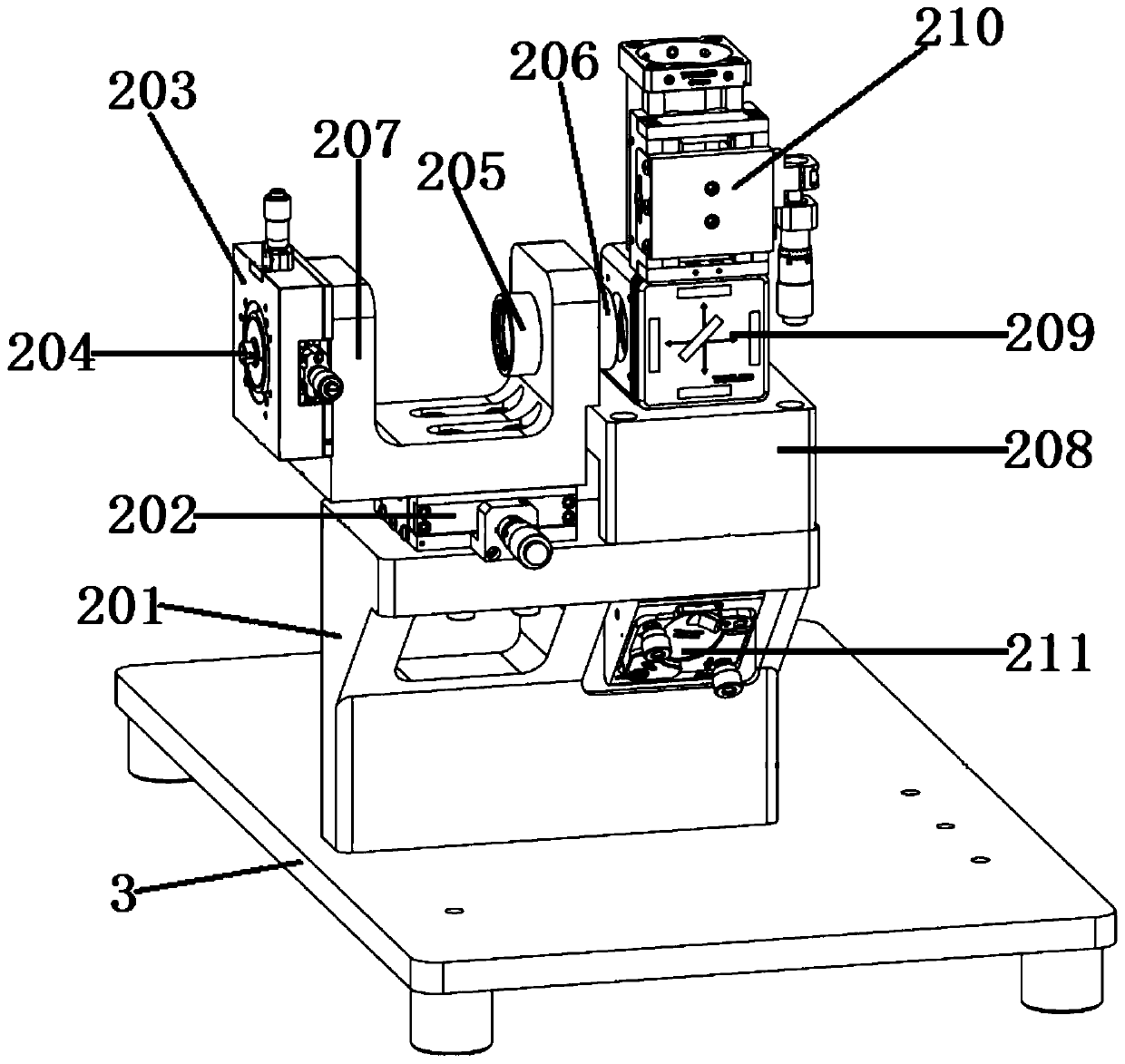
[0055] as attached figure 1 and attached figure 2 As shown, the embodiment of the present invention provides a total internal reflection fluorescence microscope that can be used in conjunction with an atomic force microscope. The total internal reflection fluorescence microscope includes: a support assembly 1, an imaging assembly 2 arranged in the inner cavity of the support assembly 1, The base 3 under the support assembly 1 , the sample stage 4 of the atomic force microscope arranged above the support assembly 1 , and the size of the support assembly 1 can be adjusted according to the size of the sample stage 4 .

[0056] The imaging assembly 2 includes a load-bearing body 201, a one-dimensional translation seat 202, a two-dimensi...


PUM


Abstract

The invention discloses a total internal reflection fluorescence microscope capable of being used with an atomic force microscope and belongs to the field of optical microscopes. The fluorescence microscope comprises a support assembly, an imaging assembly, a base, a sample objective table of the atomic force microscope. The size of the support assembly can be adjusted according to the size of the sample objective table. In the imaging assembly, a bearing body is arranged on the base, a one-dimensional translation seat is arranged on the bearing body, a second connection seat is fixed on the bearing body, a lens cone lens is arranged in an inner cavity and a reflection mirror is arranged on the bearing body and under the lens cone lens. A lower base plate of a first connection seat of a U-type structure is fixed on the one-dimensional translation seat. A two-dimensional translation seat is fixed on the outer end of a left side arm of the first connection seat. A fiber coupler is arranged in the two-dimensional translation seat in a two-dimensional moving manner. The end part of a first lens and the end part of a second lens are arranged on two ends of a second through hole of the right side arm of the first connection seat. A dichroscope assembly is arranged on the second connection seat. An objective lens is fixed on the dichroscope. The objective lens is arranged in an objective lens installation seat in a height-adjustable manner.

Description

technical field [0001] The invention relates to the field of optical microscopes, in particular to a total internal reflection fluorescence microscope which can be used in conjunction with an atomic force microscope. Background technique [0002] Total internal reflection fluorescence microscope is an optical microscope used in the field of fluorescence microscopy imaging. When the incident light undergoes total internal reflection in the optically dense medium, the evanescent field generated is on the side of the optically thinner medium (that is, the sample side) The penetration depth is only about 100nm, that is, it provides a very thin illumination depth, so the contrast of the sample fluorescence signal is much higher than that of conventional wide-field imaging. With a high-sensitivity detector, the detection limit can reach the single-molecule level, with good specificity and sensitivity. It is widely used in the real-time monitoring of molecules, microstructures, and...

Claims


Application Information

Patent Timeline
Patent Type & Authority Patents(China)
IPC IPC(8): G01Q30/02
CPCG01Q30/025
Inventor 夏铁石彦周纪松周骋
Owner IPE BIOTECHNOLOGY CO LTD
Why Eureka
Try Eureka